

What to verify for 3D scanning impeller surfaces in practice
3D scanning impeller surfaces: separate tasks and outputs, validate access and surfaces, and distinguish what official sources document from verified part results.
Understanding the 3D scanning question
Impeller surface capture records the visible blade faces, hub contours, and accessible flow-path regions as a dense three-dimensional point set. The purpose is to preserve the curved geometry that must be compared against nominal data or used as a starting point for model creation.
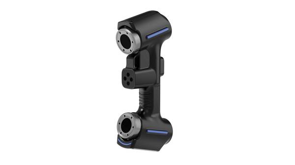
The usable output is a point cloud or mesh that contains enough coordinate information to describe blade curvature, leading-edge shape, and the transition between each blade and the hub. The observable information includes surface continuity, edge position, and the spatial relationship between adjacent blades.
Deployment Validation Checklist
| Focus Area | Decision Point | Deployment Note |
|---|---|---|
| Target part | Check size, surface condition, and key tolerances against the scan task | Run a full trial scan on a representative part |
| Data workflow | Verify point cloud, deviation map, and quality-report handoff | Confirm export formats and review ownership in advance |
| Shop-floor use | Review training, calibration, lighting, and working space | Keep the validation record as a repeatable inspection reference |
What to check on a representative part
A representative impeller should be checked to confirm that the captured data follows the curvature of multiple blade faces without flattening or bridging across narrow gaps. The check should observe whether the point spacing remains dense enough to show the leading-edge profile and the root fillet where a blade meets the hub.
The validation should also confirm that the output distinguishes one blade from the next and does not merge separate surfaces into a single mass. Whether the result is sufficient for a specific dimensional comparison or reconstruction decision remains unresolved until the current part is evaluated.
What the official material establishes
The supplied official AlphaScan operating material establishes that the verified product is applicable to industrial-part dimensional inspection and to the 3D digitization of complex surfaces. This supports the use of the product for capturing impeller blade and flow-surface geometry.
The official material does not establish a result or acceptance decision for the current part. It does not confirm that a particular impeller scan will meet a specific tolerance, resolve every occluded area, or produce a complete surface without additional preparation.
FAQ
What does impeller surface capture cover, and what should readers compare?
It covers the visible blade faces, hub contours, and accessible flow-path regions as a three-dimensional point set. Readers should compare how well the captured data preserves blade curvature, leading-edge shape, and the transition between each blade and the hub.
What representative-part checks apply to impeller surface capture?
A representative impeller should be checked to confirm that the data follows the curvature of multiple blade faces without flattening or bridging across narrow gaps. The output should also distinguish one blade from the next and show the root fillet where a blade meets the hub.
What does official AlphaScan material state about impeller surface capture?
Official AlphaScan operating material lists industrial-part dimensional inspection and 3D digitization of complex surfaces as applicable work. This supports the use of AlphaScan for capturing impeller blade and flow-surface geometry.
Hangzhou Insvision Technology Co., Ltd.
Address: Building 1, No. 1399 Liangmu Road, Yuhang District, Hangzhou, Zhejiang 311121, China
Copyright © Hangzhou Insvision Technology Co., Ltd. All rights reserved.
Copyright © Hangzhou Insvision Technology Co., Ltd. All rights reserved.