

Matching 3D Scanner Engineering Solutions to Industrial Task Requirements
Learn how to align 3D scanner engineering capabilities with first-article inspection, reverse engineering, tooling calibration, and large-assembly alignment.
Core 3D Scanner Engineering Task Classes in Modern Industrial Settings
A decade ago, a 3D scanner sat in a lab. Today, it sits next to a CNC cell, a composite layup station, or an MRO bench. The change is not just about better hardware. It is about clearer task definitions. Western manufacturers now buy scanning capability around four recurring engineering jobs: first-article inspection, reverse engineering of legacy parts, tooling and fixture calibration, and large-assembly alignment.
Teams that start with these task classes tend to select the right system. Teams that start with spec sheets often do not.
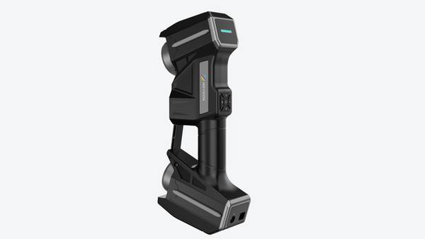
Deployment Validation Checklist
| Focus Area | Decision Point | Deployment Note |
|---|---|---|
| Target part | Check size, surface condition, and key tolerances against the scan task | Run a full trial scan on a representative part |
| Data workflow | Verify point cloud, deviation map, and quality-report handoff | Confirm export formats and review ownership in advance |
| Shop-floor use | Review training, calibration, lighting, and working space | Keep the validation record as a repeatable inspection reference |
Practical Workflow
- Core 3D Scanner Engineering Task Classes in Modern… — A decade ago, a 3D scanner sat in a lab.
- Key Operational Constraints That Narrow 3D Scanner… — Most engineers assume the hard part of 3D scanning is accuracy.
- INSVISION Portfolio Routing: Aligning Solutions to Task… — As manufacturing tolerances have tightened across medical, aerospace, and automotive supply chains, the assumption that one 3D…
- Validating Solution Fit Through Structured Engineering… — Validation is where most 3D scanning evaluations fall apart.
The most common misalignment happens when a buyer compares scanner accuracy numbers before defining how the scan data will be used. Accuracy matters, but a 0.020 mm scanner is not automatically the right tool for every job. Part size, surface finish, shop floor movement, and whether the team needs CAD comparison or mesh output all shape the decision more than a single specification.
First-article inspection remains the dominant driver in automotive OEM and medical device work. A new production part comes off the line. The quality team needs dimensional validation against the nominal CAD model before full production release. In practice, this means scanning the part, aligning the scan to the model, and reviewing a color map against GD&T callouts.
The workflow must support datum alignment and tolerance evaluation in a way that ISO and ASME Y14.5 requirements recognize. If the scan data cannot be tied back to the drawing’s datum structure, the inspection result has limited release value.
Reverse engineering for legacy part replacement is a different task class entirely. Aerospace MRO shops frequently deal with components that have no surviving CAD file or whose original drawings no longer match the worn physical part. The scanner must capture complex geometry, but the engineering challenge is in the downstream modeling step.
Teams need clean mesh data that can be converted into a parametric CAD model or used directly for toolpath generation. This is where scanner resolution and edge definition matter more than raw volumetric accuracy.
Tooling and fixture calibration is the quiet workhorse of 3D scanner engineering. A fixture drifts over time. A welding jig gets knocked. A composite mold changes shape after repeated thermal cycles. Instead of sending the tool out for CMM measurement, production teams scan the tool in place and compare it to its original CAD or a previously captured baseline scan. The value is speed and reduced downtime.
The technical requirement is repeatability across multiple scans, not just single-scan accuracy. If the scanner cannot produce stable results across different operators and shifts, the calibration data becomes unreliable.
Large-assembly alignment is the fourth task class, and it is growing in renewable energy and aerospace structures. Wind turbine hubs, wing spars, and large weldments present a different problem: the part is too big for a single scan volume. The scanner must either move around the part with tracking support or the team must stitch multiple scans using reference targets.
For large-assembly work, the tracker’s range matters because it determines how much of the assembly can be captured before repositioning.
The practical takeaway for Western engineering teams is straightforward. Before evaluating any 3D scanner, classify the work. Is it first-article inspection, reverse engineering, tooling calibration, or large-assembly alignment? Each task class has different requirements for accuracy, repeatability, scan volume, and downstream data format.
INSVISION supports these workflows through scanner and tracker configurations that prioritize task fit over headline specifications. The right conversation starts with the part, the tolerance, and the intended use of the data. The hardware decision follows from there.
Key Operational Constraints That Narrow 3D Scanner Engineering Selection
Most engineers assume the hard part of 3D scanning is accuracy. It is not. The real filter is operational fit. A scanner that works beautifully in a climate-controlled metrology lab can become dead weight on a wind farm service truck or inside an aerospace MRO hangar where the target part cannot be disassembled, marked, or moved.
For Western engineering teams, five constraints narrow the shortlist faster than any specification sheet. First, part size range. The same workflow that captures a sub-centimeter medical implant will fail on a 20-meter composite blade unless the scanner and tracker carry enough depth of field and scanning area.
Those numbers matter less as marketing claims and more as evidence that one platform can stretch across small-part and large-assembly jobs without switching systems.
Second, site deployment. A fixed quality lab is one environment. A shop floor next to a machining cell is another. Remote field MRO is a third. Equipment weight, setup time, environmental tolerance, and whether the scanner can run without a controlled temperature band determine whether the tool gets used or stays in its case. Third, marker application.
Many medical and aerospace parts cannot accept adhesive targets because of cleanroom rules, material sensitivity, or regulatory limits. Marker-free or marker-light workflows stop being a convenience and become a compliance requirement.
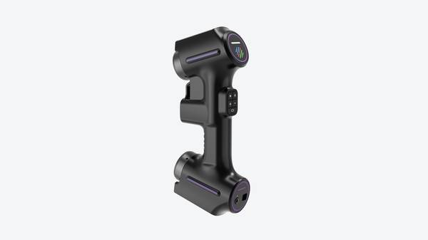
Fourth, takt time. High-volume batch production needs scanning speed that keeps pace with the line. Low-volume custom projects tolerate slower, more iterative capture. Fifth, batch repeatability. One-time reverse engineering and ongoing production inspection are different jobs with different software, reporting, and traceability needs.
Teams that ignore this distinction end up with a scanner that collects data but cannot support first-article inspection or CAD comparison in a repeatable, audit-ready way.
Each constraint maps to a real pain point. Aerospace MRO crews scanning on-wing components cannot strip paint or apply markers. Medical device teams working under cleanroom protocols cannot introduce adhesive residue. Energy field teams need to scan tower sections and blade roots without scaffolding or controlled lighting. The viable 3D scanner engineering selection is not the most accurate device on paper.
It is the one that fits the part, the site, the marker rules, the cycle time, and the repeatability demand of the actual job.
INSVISION Portfolio Routing: Aligning Solutions to Task and Constraint Profiles
As manufacturing tolerances have tightened across medical, aerospace, and automotive supply chains, the assumption that one 3D scanner can cover every engineering task has quietly collapsed. We see this most clearly in first-article inspection and production part approval workflows. A scanner that performs well on a small orthopedic implant often becomes a bottleneck when moved to an aircraft wing spar.
The issue is not raw accuracy alone, but how the system behaves under specific constraints: part size, site access, surface finish, marker placement, cycle time, and repeatability across shifts.
INSVISION has moved away from generic product recommendations. The portfolio routing process starts with the task profile, not the specification sheet. That means asking what the team actually needs to capture, where the measurement takes place, and what downstream software consumes the data.
The result is a better match between engineering constraints and scanning capability, which reduces the hidden costs of rework, rescanning, and operator frustration.
Small high-precision medical parts with tight GD&T callouts, for example, demand micron-level detail capture and stable repeatability across small batch runs. In these cases, INSVISION routes teams toward solutions that excel at capturing fine surface detail and handling delicate geometries without excessive setup time. The scanner becomes an inspection tool rather than a laboratory curiosity.
Large aerospace assembly alignment is a different problem entirely. Here the dominant constraints are wide-area measurement, on-site deployment, and tolerance verification across long distances. INSVISION solutions suited to this profile are built for field use and large scanning volumes, so teams can align major structures without moving them to a climate-controlled metrology lab.
This matters in MRO hangars and final assembly lines where downtime is measured in hours, not minutes.
High-throughput repeat inspection in automotive or energy settings introduces yet another profile. The scanner must deliver consistent results across dozens or hundreds of parts per shift, with minimal operator intervention. INSVISION routing accounts for takt time and batch repeatability, directing buyers toward systems optimized for fast, repeatable capture rather than one-off reverse engineering projects.
Across all these profiles, INSVISION 3D scanning solutions support core engineering workflows: dimensional inspection, CAD comparison, and reverse engineering. Compatibility with leading industrial CAD and quality software platforms used in Western markets means the scan data flows into existing PPAP, FAI, and nonconformance processes without forcing a software overhaul.
The practical takeaway is that selection should begin with the constraint profile, not the scanner brochure. Engineers and quality managers should document part size, site freedom, marker conditions, required throughput, and downstream data use before evaluating hardware. INSVISION’s consultative routing process aligns each combination to a solution that fits the task, avoiding both over-specification and underperformance.
Validating Solution Fit Through Structured Engineering Sample Testing
Validation is where most 3D scanning evaluations fall apart. Not because the hardware lacks capability, but because the test never matched the actual engineering workload. A scanner that performs well on a clean demo part in a controlled lab can struggle on a production floor with vibration, temperature swings, and parts that carry real manufacturing variation. Western quality managers recognize this gap.
ISO 9001 and AS9100 frameworks demand evidence, not vendor assurances.
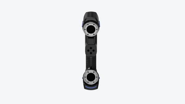
INSVISION approaches this by working directly with engineering teams during the validation phase. The process starts before any scanning happens. Define the critical feature tolerances and measurement priorities upfront. If a bore position must hold ±0.050 mm, that tolerance drives the test protocol. Without this step, validation becomes a demo rather than an engineering exercise.
The test part matters just as much as the scanner. A representative component with known, calibrated measurement benchmarks gives you a reference standard. You need a part that has been independently measured, ideally on a CMM, so scan data can be compared against trusted values. This is not about showing impressive point clouds. It is about confirming that deviation maps reflect reality.
Data compatibility is the silent killer in many 3D scanner engineering evaluations. A scanner can produce excellent mesh data that your PLM system cannot ingest without conversion scripts and manual cleanup. Before committing, confirm that scan output flows into existing CAD, PLM, and QMS workflows.
If your team uses CATIA or NX for comparison, the scan software must export formats those platforms accept without loss of fidelity. INSVISION tests this directly against your actual parts and workflows, not generic sample files.
Operator training requirements deserve honest assessment. Some systems demand weeks of specialized training before producing repeatable results. Others can be run by quality technicians after a short onboarding period. The right answer depends on your team structure and turnover rates. During validation, have the people who will actually operate the equipment run the tests.
That reveals whether the solution fits your organization or just your expert evaluator.
Site conditions cannot be simulated in a vendor showroom. Shop floor vibration, ambient temperature variation, and lighting conditions all affect scanner performance. Validation should happen where the equipment will live. INSVISION supports this by testing solutions under actual environmental conditions, confirming that accuracy claims hold when the machine next to the scanner is running and the bay door opens in winter.
The goal of structured sample testing is not to find the most impressive scanner. It is to find the solution that fits your engineering requirements with the least operational friction. That is a different question, and it requires a different evaluation method.
Actionable Decision Checklist for 3D Scanner Engineering Selection
Are your quality, engineering, and procurement teams actually aligned on what “good enough” means for a 3D scanner purchase? In most plants, the answer is no. One group cares about GD&T verification, another worries about shop-floor durability, and procurement wants to avoid paying for capability nobody uses. A cross-functional checklist solves this. It forces the conversation away from spec sheets and toward operational fit.
Start with core task requirements. Can you document GD&T callouts for every critical feature, or are you still working from tribal knowledge? If the latter, fix that before scanning anything. Next, operational constraints: will this unit live in a lab, travel to a field site, or both? Environmental exposure, vibration, and setup time matter as much as accuracy. Integration needs come third.
Scan data must flow into your existing CAD, PLM, or inspection software without manual rework. Finally, long-term scalability. If automated inspection is on your two-year roadmap, buying a handheld-only solution today creates a dead end.
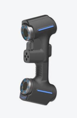
Weight these categories by your primary use case. A job shop reverse-engineering castings has different priorities than an aerospace supplier doing first-article inspection. INSVISION 3D scanner engineering tools support this kind of weighted evaluation because the product line spans portable scanning, tracked large-volume capture, and automated options.
That breadth lets teams match capability to task instead of forcing one device into every role. Procurement should demand evidence for each checklist item, not marketing language. Ask for a documented accuracy test on a part similar to yours, a live software export into your CAD format, and a site walkdown with the actual unit. If a vendor cannot provide those, the checklist has done its job.
Hangzhou Insvision Technology Co., Ltd.
Address: Building 1, No. 1399 Liangmu Road, Yuhang District, Hangzhou, Zhejiang 311121, China
Copyright © Hangzhou Insvision Technology Co., Ltd. All rights reserved.
Copyright © Hangzhou Insvision Technology Co., Ltd. All rights reserved.