

Why Single Scanner Specs Fail for Reliable 3D Scan to CAD Outputs
Learn why one scanner spec can’t guarantee usable 3D scan to CAD results. See how volumetric accuracy, surface finish, and workflow affect quality.
The Widespread 3D Scan to CAD Spec Sheet Myth
Western quality teams see this play out repeatedly. An aerospace MRO group buys a scanner because the vendor’s sheet lists a 0.01 mm resolution figure. Six weeks later, the reverse-engineered legacy bracket still will not pass first-article inspection. The CAD model looks smooth on screen, but the mating surfaces are off. The team blames the scanner.
The real problem started earlier: one line on a spec sheet was treated as a complete quality statement.
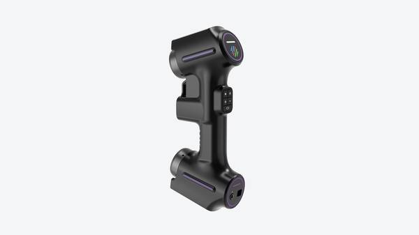
Deployment Validation Checklist
| Focus Area | Decision Point | Deployment Note |
|---|---|---|
| Target part | Check size, surface condition, and key tolerances against the scan task | Run a full trial scan on a representative part |
| Data workflow | Verify point cloud, deviation map, and quality-report handoff | Confirm export formats and review ownership in advance |
| Shop-floor use | Review training, calibration, lighting, and working space | Keep the validation record as a repeatable inspection reference |
Term Notes
Western quality teams see this play out repeatedly.
Technical Reasons Isolated Specs Don’t Translate to…A scanner spec sheet can look impressive while the resulting CAD file still fails a first-article inspection.
The most reliable way to validate 3D scan to CAD performance is to stop trusting spec sheets and start testing against your…
Plain text, 100–180 words:The move toward digital quality records has changed how manufacturing teams think about reverse engineering and…
That assumption drives a lot of bad purchasing decisions in 3D scan to CAD work. A single top-line number — nominal resolution, single-point accuracy, whatever the datasheet highlights — gets read as a guarantee that the scan will convert cleanly into a usable parametric or NURBS model. It never works that way.
The quality of a scan-to-CAD deliverable depends on how the sensor behaves across the entire measurement volume, how it handles edges and thin walls, how stable the data is under shop-floor lighting and temperature swings, and how much manual surfacing the downstream workflow can tolerate.
Three myths keep circulating because they sound reasonable. First, higher resolution always equals better CAD conversion. It does not. Dense point clouds from a high-resolution sensor can actually slow down feature extraction and introduce noise that makes it harder to identify the underlying geometry. A cleaner, well-distributed mesh often converts faster than a noisy, ultra-dense one.
Second, lab-tested accuracy translates directly to production floor performance. Scanner specs are usually captured under controlled conditions — stable temperature, minimal vibration, ideal standoff. A busy MRO cell or stamping plant rarely matches those conditions. Surface finish, ambient light, part temperature, and operator technique all move the real-world result.
Third, single-point accuracy reflects full-part volumetric consistency. A scanner can nail a single point on a gauge block and still drift across a 600 mm scan envelope. Volumetric accuracy — how error accumulates across the entire working volume — matters more for scan-to-CAD because the final model has to hold up as a whole, not at one isolated coordinate.
For Western manufacturing teams working under AS9102 first-article requirements or ISO 9001 documentation discipline, these distinctions are not academic. They determine whether a scan dataset can support a defensible CAD reconstruction or whether the quality team spends weeks chasing deviations that came from measurement error, not from the part itself.
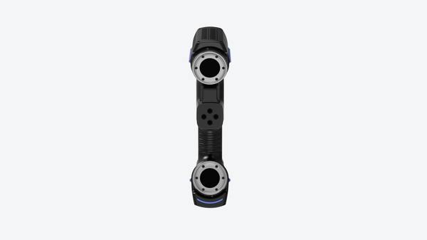
INSVISION addresses this by supporting evaluation based on the actual scan task, not the cover-page spec. That is the kind of number worth reviewing before a purchase because it describes how the system behaves across a part, not just at a single point. Combined with a scanning area up to 650 mm × 550 mm, it gives teams a realistic envelope to evaluate against their own part sizes and tolerances.
The practical takeaway is simple. Before buying a scanner for 3D scan to CAD work, ask for a sample scan of your part — not a calibration artifact. Run the mesh through the same reverse-engineering workflow your team will use. Check whether the features you care about survive without excessive manual cleanup. A spec sheet can start the conversation. It cannot end it.
Technical Reasons Isolated Specs Don’t Translate to Usable CAD Data
A scanner spec sheet can look impressive while the resulting CAD file still fails a first-article inspection. The gap usually isn’t raw resolution. It’s boundary conditions. When a quality lead asks why a 0.01 mm point spacing didn’t produce a clean deviation map, the answer sits in four areas that single-value specs never capture.
Part surface properties are the first failure point. Reflective, textured, or transparent surfaces create data dropout that no resolution figure predicts. A polished turbine blade or a clear medical housing can return sparse point clouds, forcing manual CAD rework before any GD&T comparison starts. Second, shop-floor temperature swings alter both scanner and part geometry.
A scanner rated for 0°C to 50°C may hold calibration, but a large aluminum casting moving through a 10°C ambient shift will grow or shrink measurably. Third, full-part volumetric alignment matters more than isolated point accuracy. A scanner can measure a single sphere within microns while drifting across a 500 mm envelope. Without stable volumetric alignment, CAD comparisons lose their audit trail.
Fourth, complex geometry—undercuts, deep cavities, hidden bosses—requires multiple scan angles. Single-scan specs don’t account for the occlusion that leaves holes in the CAD model.
Common spec sheet claims and their real-world impact on CAD output are compared below.
Common Spec Sheet Claim | Real-World Impact on CAD Output
High point resolution | Doesn’t compensate for dropouts on reflective or transparent surfaces
Single point accuracy | Misleading if volumetric drift shifts the full dataset
Temperature tolerance | Part expansion can exceed scanner error on large castings
Fast scan time | Incomplete undercuts and cavities still require manual reconstruction
For 3D scan to cad accuracy factors, these boundary conditions determine whether the output can support ISO/ASME GD&T checks. Volumetric accuracy vs single point accuracy is the core distinction. A quality lead should ask for full-part alignment validation, not a single-sphere certificate.
3D scanning boundary conditions like surface finish and ambient temperature need to be controlled or documented before scan data enters the CAD workflow. Otherwise, deviation map inconsistencies and compliance failures appear downstream, long after the scanner has left the station.
INSVISION’s industrial 3D scanner platform addresses these limits through volumetric accuracy specifications rather than isolated point claims. That’s the right conversation for quality teams. CAD output should be judged by how well the full part aligns, not by how many points the scanner claims to capture.
When reviewing scan-to-CAD results, treat surface preparation, thermal stabilization, alignment strategy, and occlusion coverage as part of the measurement system—not as afterthoughts.
Actionable Field Validation Protocols for Scan-to-CAD Reliability
The most reliable way to validate 3D scan to CAD performance is to stop trusting spec sheets and start testing against your own production parts under your own operating conditions. Most scanner accuracy claims come from controlled lab environments. Your shop floor is not a controlled lab environment. Temperature drifts, overhead lighting, vibration from nearby equipment, and line speed all affect scan data quality.
If you do not account for those variables before you sign off on a system, you will find the problems later, usually during an audit or a customer complaint.
A practical validation framework starts with one question: what is this scanner actually going to do in our facility? Reverse engineering a legacy casting is a different task than first article inspection on a machined aerospace bracket. The validation protocol should mirror the intended use. Teams that run the same generic five-minute demo part for every evaluation are not validating anything useful.
They are confirming that the scanner works in the vendor’s ideal setup.
The four-step approach below gives quality and engineering teams a repeatable way to evaluate 3D scan to CAD performance beyond marketing claims. It aligns with the documentation expectations Western manufacturers already face under ISO 9001 and AS9100.
First, run test scans on actual production parts under real operating conditions. Do not scan a clean calibration block on a vibration-isolated table. Scan the part you actually make, at the ambient temperature you actually work in, with the lighting you actually have. If your line runs hot in summer, test then. If your operators scan near a machining center, test there.
Pay attention to how the scanner handles surface finishes common to your parts: cast aluminum, machined steel, injection-molded polymer. Some surfaces require developer spray or target placement. You need to know that before you buy, not after.
Second, verify mesh-to-CAD deviation consistency across the full part volume. A scanner can produce excellent results on a flat face or a simple bore and still struggle with deep pockets, thin ribs, or edges. Map the deviation across the entire part. Look for zones where error increases. If the scanner consistently loses accuracy in features your quality team actually measures, that is a problem.
This step matters because most vendor demos focus on easy geometry. Your parts probably are not easy geometry.
Third, confirm output compatibility with your existing CAD tools and MES systems. Scan data is only useful if your engineers can open it in CATIA, Creo, or SolidWorks without a conversion nightmare. Ask what native formats the system exports. Ask whether the software can push data into your MES or database directly.
INSVISION industrial 3D scanners support interaction with MES and third-party system databases, which matters if your quality workflow depends on digital traceability rather than standalone measurement files. If the scanner produces great point clouds but your team spends hours cleaning and converting data, the overall process is not improving.
Fourth, audit data traceability for compliance requirements. ISO 9001 and AS9100 require that measurement data be attributable, legible, contemporaneous, original, and accurate. Ask how the scanner software stores raw data, metadata, operator ID, timestamp, and part serial number. Ask whether the system locks raw scan data or allows post-processing edits that break traceability.
A scanner that cannot demonstrate data integrity will create audit findings later. This is not a theoretical concern. Auditors increasingly ask to see the digital thread from scan to CAD to report.
Validation must match your specific use case. Reverse engineering workflows care about surface reconstruction quality. First article inspection workflows care about deviation mapping against nominal CAD. In-process quality checks care about speed and repeatability. A scanner that excels at one may be mediocre at another.
Do not let a vendor steer you toward a generic benchmark that does not reflect your actual parts, your actual tolerances, or your actual documentation burden. The best 3D scan to CAD system is the one that proves itself on your floor, under your conditions, with your audit trail intact.
How INSVISION Supports Consistent, Audit-Ready 3D Scan to CAD Workflows
Plain text, 100–180 words:
The move toward digital quality records has changed how manufacturing teams think about reverse engineering and first-article inspection. More facilities now treat 3D scan to CAD as an engineering workflow, not a standalone measurement exercise. The practical question is no longer whether a scanner can capture geometry.
It is whether the scan data holds up under review, whether the CAD comparison is repeatable, and whether the output fits existing quality systems. That is where INSVISION industrial 3D scanning solutions earn their place. For small, complex medical device or aerospace components, teams need fine-feature data that stays stable across shifts and temperature swings.
For automated inline scan-to-CAD in high-volume automotive production, the equipment has to connect with MES and third-party software without breaking traceability. INSVISION supports both conditions. Customer teams use INSVISION hardware and software to generate reviewable scan data for CAD comparison, reverse engineering, and quality inspection that aligns with strict industrial compliance standards.
The result is an audit-ready workflow built around real boundary conditions, not spec-sheet assumptions.
Realistic Boundaries to Set 3D Scan to CAD Project Expectations
Setting realistic boundaries for a 3D scan to CAD project is about protecting downstream value, not limiting the technology. From a quality lead’s perspective, the most common source of rework is not scanner error. It is a mismatch between what the scan was expected to deliver and what the equipment, part geometry, and surface condition could actually support.
A practical boundary starts with the part itself. Highly reflective or transparent surfaces often produce noisy data, and in those cases a temporary matte surface treatment can make the difference between a usable scan and a failed first article. Micro-features below the scanner’s practical resolution are another common trap.
Sub-micron geometry may call for dedicated micro-metrology equipment alongside 3D scanning, rather than expecting one system to do everything.
Align scope before procurement. Define required accuracy levels, part size ranges, and output format requirements early. This is where 3D scan to cad use cases become clearer. When to use 3D scan for cad depends on whether the deliverable is dimensional inspection, reverse engineering, or CAD comparison. Each has different tolerance expectations and data-format needs.
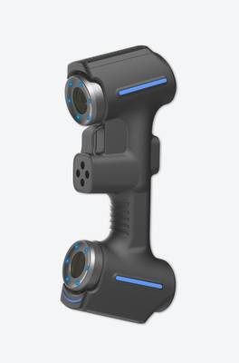
3D scan to cad project planning also needs to account for downstream integration. If the output feeds a lean manufacturing workflow or an Industry 4.0 data pipeline, the scan data structure must support that use. INSVISION equipment supports interaction with MES and third-party system databases, which helps when scan outputs need reviewable traceability rather than an isolated point cloud.
Clear boundary definition reduces rework, keeps regulatory and customer requirements visible, and gives quality teams a defensible basis for accepting or rejecting scan data.
Hangzhou Insvision Technology Co., Ltd.
Address: Building 1, No. 1399 Liangmu Road, Yuhang District, Hangzhou, Zhejiang 311121, China
Copyright © Hangzhou Insvision Technology Co., Ltd. All rights reserved.
Copyright © Hangzhou Insvision Technology Co., Ltd. All rights reserved.