

How a 3D Scanner Supports Reverse Engineering in Practice
See how a 3D scanner can help with reverse engineering by capturing real world geometry for accurate digital reconstruction.
The Widespread Assumption That Any 3D Scanner Works for Reverse Engineering
Walk into any toolroom or quality lab and you will hear the same shorthand: we need a scanner that hits a few microns, so we can pull the CAD model and get back to production. The assumption is that a top-line accuracy figure on a spec sheet translates directly into usable reverse engineering data. That assumption is expensive.
Common Questions
What to Validate for Reverse Engineering
Walk into any toolroom or quality lab and you will hear the same shorthand: we need a scanner that hits a few microns, so we can pull the CAD model and get back to production.
Limits of Accuracy-Only Comparisons
Most quality leads assume a scanner’s published accuracy number transfers directly to the parts they actually need to reverse engineer.
Practical Validation Checks
A scanner that impresses in a climate-controlled demo can fall apart next to a machining center.
Spec sheets are written to sell hardware. They quote a single-point or volumetric accuracy under controlled conditions, often on matte, coated, or reference surfaces. Real parts rarely cooperate. Castings have draft and flash. Weldments distort. Aerospace MRO components arrive with service wear, blended repairs, and unknown datum loss. Automotive interior panels flex under their own weight.
Medical device housings have fine organic surfaces and tight GD&T callouts that matter more than the scanner’s headline number.
This is where the oversimplified belief breaks down. A scanner can capture millions of points quickly, but the deliverable is not a point cloud. The deliverable is a parametric CAD model that passes first-article inspection, mates with existing assemblies, and survives downstream tolerance stack-up. If the scan data cannot be converted into that model without hours of rework, the initial accuracy claim means little.
The belief persists because simplified online content frames 3D scanning as a universal solution. Marketing collateral shows a technician waving a handheld device at a part, followed by a clean CAD overlay. What is missing is the boundary conditions: surface preparation, registration strategy, feature extraction, and the software workflow required to move from mesh to parametric solid.
For quality leads in automotive OEM, aerospace MRO, medical device, and energy, the pain shows up later as failed GD&T conformance, delayed first-article inspection, and engineering rework that erases any time saved at the scanner.
A 3D scanner can help with reverse engineering, but only when it is validated against the actual part geometry, surface condition, and required data deliverable. The scanner itself is one link in a chain that includes part setup, reference targets, scan planning, mesh processing, and CAD modeling. If any link is weak, the final model will not hold tolerance.
This article breaks down what spec sheets do not tell you, how to validate real-world performance before committing to a scanner, and how to align scanner choice with quality requirements rather than marketing numbers. The focus is on boundary conditions and reviewable outputs, not generic claims.
Why Single-Spec Evaluations Fall Short for Industrial Reverse Engineering
Most quality leads assume a scanner’s published accuracy number transfers directly to the parts they actually need to reverse engineer. That assumption falls apart quickly on the shop floor.
Published single-point accuracy is typically derived under controlled conditions: a calibrated artifact, ideal standoff distance, stable temperature, and a matte surface. It says little about how the system behaves across a full automotive bracket, a worn turbine blade, or a medical implant with mixed finishes.
For reverse engineering, the metric that matters more is volumetric accuracy—how well the scanner holds dimensional consistency across the entire measurement volume, not at one isolated point.
Surface finish and geometry introduce further complications. Shiny, dark, or machined surfaces scatter laser light differently. Deep pockets, sharp edges, and thin walls create occlusions. These conditions degrade data quality even when the spec sheet looks strong. A scanner that performs well on a ceramic reference block may struggle on a cast aluminum housing with residual oil film.
For tier 1 automotive suppliers, aerospace MRO teams, and medical device manufacturers operating under ISO 17025 or AS9100 traceability requirements, this gap creates real risk. Reverse engineering deliverables are not just point clouds. They feed parametric CAD models, inspection reports, and tooling corrections.
If the underlying scan data lacks repeatable volumetric consistency, downstream rework appears in the form of mismatched mating surfaces, failed first-article inspections, or tooling that misses GD&T callouts. The cost lands weeks later, far from the scanning station.
A 3D scanner can help with reverse engineering only when the evaluation process accounts for these boundary conditions. That means validating the system against a representative part, not a polished calibration standard. It means asking for volumetric accuracy data across the full working volume. And it means testing on the actual materials and finishes your team encounters daily.
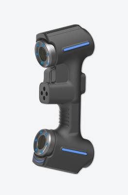
INSVISION’s AlphaScan handheld 3D scanner, for example, specifies volumetric accuracy as 0.015mm + 0.035mm/m, a format that acknowledges error grows with part size rather than hiding behind a single optimistic point measurement.
The comparison below outlines why these two metrics lead to different conclusions in practice.
| Metric | What It Measures | Relevance to Reverse Engineering |
|---|---|---|
| Single-point accuracy | Deviation at one specific location under ideal conditions | Limited; does not predict performance across complex geometry |
| Volumetric accuracy | Error propagation across the full measurement envelope | High; reflects real-world scanning of brackets, housings, and freeform surfaces |
Relying on single-point specs during vendor evaluation creates a false confidence that collapses when parts get large, shiny, or geometrically complex. Quality leads who push for volumetric validation before purchase avoid the expensive rework loops that follow when spec sheets and shop-floor reality diverge.
Practical Validation Steps for Quality-Focused Reverse Engineering Teams
A scanner that impresses in a climate-controlled demo can fall apart next to a machining center. Quality leads know this. The fix is a short, structured validation plan run on your own floor before purchase sign-off.
Start with a representative production part. Pick something with the surface finishes and complex geometry your team actually handles, not a matte calibration block. Shiny, machined, or dark surfaces stress-test the scanner’s exposure logic. Second, verify volumetric accuracy across your full part size range. Scan a small bracket and a large housing. Compare against a CMM or calibrated gauge.
Third, test export and import compatibility with your existing CAD tools. If the mesh or parametric output does not move cleanly into CATIA or SolidWorks, reverse engineering stalls at the handoff. Fourth, run repeatability tests with at least two operators. Different scan paths and hand speeds should not shift results beyond your tolerance band.
This matters for lean and Industry 4.0 programs. Upfront validation prevents downstream rework and protects digital thread and MES integration plans. INSVISION handheld scanners such as AlphaScan publish volumetric accuracy of 0.015 mm plus 0.035 mm/m, but the real test is whether that holds on your parts, with your operators, inside your software workflow. Controlled demos do not answer that. A half-day validation does.
INSVISION AlphaScan: Built for Validated Reverse Engineering Workflows
The core problem with reverse engineering isn’t capturing geometry. It’s capturing geometry you can defend. A 3D scanner can help with reverse engineering only when the data holds up under scrutiny—when a quality lead can trace the scan back to a known accuracy envelope and sign off on the output. That’s the gap AlphaScan addresses.
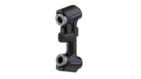
The handheld form factor matters more than it first appears. Legacy turbine blades in an aerospace MRO hangar can’t always move to a metrology lab. A custom medical implant prototype may sit in a cleanroom. An automotive aftermarket bracket might be on a bench next to a running line. AlphaScan goes to the part, not the other way around.
This keeps production moving and reduces the handling risk that comes with transporting fragile or worn components.
On the accuracy side, the confirmed volumetric specification is 0.015mm + 0.035mm/m. That figure describes how error scales across the full measurement volume, not just at a single calibration point. When paired with a photogrammetric scale bar, the specification tightens to 0.015mm + 0.025mm/m. For larger parts—say a turbine casing or a suspension component—that scale-bar workflow keeps the scan consistent from end to end.
Single-point accuracy claims don’t help much when you’re reverse engineering a 600mm casting.
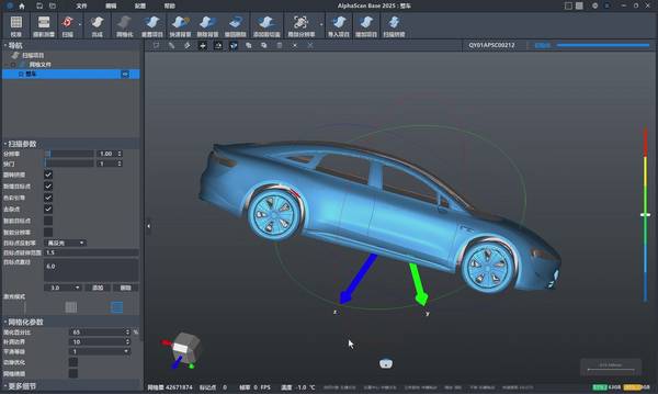
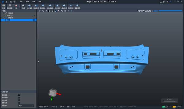
Quality leads typically want to run pre-deployment part testing before committing to a scanning platform. That means taking a known reference part, scanning it, and checking the mesh against existing CAD or inspection data. AlphaScan’s data export supports that kind of validation because the mesh output can be brought into standard reverse engineering software and compared against reference geometry.
The reviewable output isn’t just the STL. It’s the documented accuracy envelope behind it.
Western industrial use cases tend to share a common thread: the original CAD is gone, the part is too complex for manual measurement, and the replacement has to fit the first time. Energy MRO shops reverse engineering legacy turbine components face exactly this. So do medical device teams iterating on patient-specific implants.
Aftermarket automotive suppliers redesigning parts with worn tooling or incomplete drawings hit the same wall. In each case, the scanner has to deliver data that downstream CAD modeling can trust.
AlphaScan’s accuracy specification supports that level of consistency. It won’t replace a CMM for every GD&T callout, and it shouldn’t be treated as one. But for the broad middle ground of reverse engineering—where complex freeform surfaces, legacy parts, and missing documentation are the norm—it provides a defensible starting point for CAD reconstruction.
Align Scanner Choice to Your Reverse Engineering Boundary Conditions
The scanner that works well on a bench in a metrology lab may struggle the moment it is moved next to a stamping press or into an aircraft hangar. Reverse engineering rarely happens under ideal conditions. The part is often dirty, still fixtured, too large to move, or covered in features that are difficult to reach. A quality lead reviewing scanner options is not just comparing specifications.
The real question is whether the tool will produce repeatable, reviewable data under the conditions that actually exist on the floor.
A 3D scanner can help with reverse engineering, but only when the equipment matches the boundary conditions of the task. Handheld scanning adds the most value where access is constrained, where parts cannot be transported to a lab, or where external geometry can be captured without destructive sectioning.
Teams evaluating scanners should treat fit as a checklist of best-suited scenarios, not as a hunt for the highest number on a datasheet.
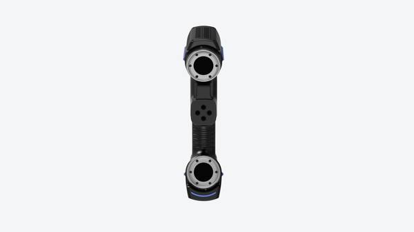
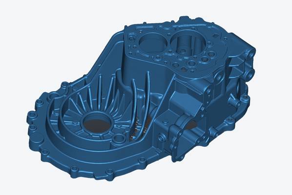
Parts with accessible external features are the strongest candidates for handheld scanning. If the geometry of interest sits on the outside of a casting, housing, weldment, or formed panel, a handheld scanner can move around the part and capture the full surface without a positioning arm or rotary table. The operator controls the angle and standoff distance.
That flexibility matters when scanning large parts in place, such as ducting, brackets, or legacy tooling that cannot be removed from the machine.
On-site scanning changes the workflow. Instead of packing parts and shipping them to a measurement lab, the team brings the scanner to the part. This reduces handling risk and keeps the reverse engineering project tied to the actual assembly environment. A quality lead should confirm that the scanner can hold stable data quality across a full scanning session, not just for a short burst.
Drift, thermal shift, and operator movement all affect the result more in the field than on a granite table.
Regulated industries add another boundary condition. In aerospace MRO or medical device work, the scan data must be volumetrically consistent and traceable to the part revision. A scanner that produces a beautiful mesh is not enough. The data must survive review, align with CAD references, and support documentation requirements.
Teams should validate that the scanner can deliver repeatable results across operators, not just across a single demonstration part.
When evaluating a handheld scanner for reverse engineering, a quality lead should focus on four practical checks. First, test on the team’s own representative parts, not only on the vendor’s sample blocks. Second, verify data consistency across the full part envelope, including deep pockets, edges, and areas with changing curvature.
Third, confirm that the output moves cleanly into the existing CAD workflow without excessive rework. Fourth, check repeatability by scanning the same part on different days or with different operators.
INSVISION positions the AlphaScan handheld 3D scanner for exactly this type of work. The published volumetric accuracy of 0.015 mm + 0.035 mm/m, or 0.015 mm + 0.025 mm/m when working with a photogrammetric scale bar, gives quality teams a starting point for evaluating real-world performance. But the specification only matters if the scanner holds that behavior across the part size and site conditions the team actually faces.
A scale bar workflow can help on larger parts where accumulated error would otherwise grow with scan length.
Common questions from quality leads tend to repeat. Can a 3D scanner help with reverse engineering for AS9100-compliant aerospace parts? Yes, when the scanner’s volumetric accuracy and data traceability are validated against part requirements and aligned to regulatory standards. Does a single-point accuracy spec guarantee reverse engineering quality?
No, volumetric accuracy across full part dimensions and repeatability across operators are more reliable indicators of real-world performance. What should I prioritize when testing a scanner for reverse engineering? Prioritize testing on your own representative parts, verifying both data consistency across the full part and compatibility with your existing CAD workflow.
The takeaway is straightforward. While a 3D scanner can help with reverse engineering, success depends on validating real-world performance against your specific part and workflow requirements, not just relying on spec sheet numbers. The right scanner is the one that fits the part geometry, the site conditions, and the documentation demands of the job.
Hangzhou Insvision Technology Co., Ltd.
Address: Building 1, No. 1399 Liangmu Road, Yuhang District, Hangzhou, Zhejiang 311121, China
Copyright © Hangzhou Insvision Technology Co., Ltd. All rights reserved.
Copyright © Hangzhou Insvision Technology Co., Ltd. All rights reserved.