

How to Evaluate calibry 3D scanner for Industrial Inspection
Learn the Calibry 3D scanner workflow from station setup and part capture to deviation reporting and reinspection triggers for continuous quality.
Shop-Floor Quality Handoff Gaps in Manual Inspection Workflows
Western manufacturing teams keep circling back to the same frustration: the part is finished at the station, but the quality verdict lags by hours or days. A machinist completes an automotive bracket, an MRO technician preps a turbine component, a medical device cell finishes a titanium implant — then everything waits. Calipers check a few critical dimensions. A fixed CMM queues behind three other jobs.
The production team moves on, while rework decisions sit in limbo.
Key Points at a Glance
- Western manufacturing teams keep circling back to the same frustration: the part is finished at the station, but the quality verdict lags by hou…
- The push toward tighter traceability requirements in automotive and aerospace supply chains has changed how metrology teams prepare for inspecti…
- Most people assume a 3D scanner either captures everything or misses everything.
- What happens when a point cloud flags an out-of-tolerance feature at 2:30 PM on a Tuesday?
That handoff gap is where cost compounds. A nonconformance found late means the batch, the fixture, and the machine program are all suspect. Rework corrections arrive after the operator has lost setup context. And for ISO/ASME traceability, the paper trail becomes a reconstruction exercise rather than a live record.
Deployment Validation Checklist
| Focus Area | Decision Point | Deployment Note |
|---|---|---|
| Target part | Check size, surface condition, and key tolerances against the scan task | Run a full trial scan on a representative part |
| Data workflow | Verify point cloud, deviation map, and quality-report handoff | Confirm export formats and review ownership in advance |
| Shop-floor use | Review training, calibration, lighting, and working space | Keep the validation record as a repeatable inspection reference |
Teams researching portable metrology tools like the Calibry 3D scanner are usually responding to this exact misalignment: station actions happen in real time, but inspection data and exception resolution do not. Closing that gap is less about measurement speed and more about restoring a single, continuous quality loop on the floor.
Pre-Scan Station Setup and Cross-Team Alignment Steps
The push toward tighter traceability requirements in automotive and aerospace supply chains has changed how metrology teams prepare for inspection work. More plants now treat the pre-scan phase as a formal workflow step rather than a loose collection of setup tasks. That shift matters because misalignment between production, quality, and engineering before scanning starts is the most common source of wasted measurement cycles.
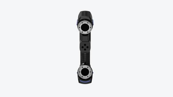
Station-level preparation begins with the production team marking part identification numbers and critical feature zones directly on the component, following the engineering drawing. This step removes guesswork later. Quality personnel then preload GD&T requirements and reference CAD files into the scanning software.
INSVISION industrial 3D scanning solutions support direct import of standard CAD and GD&T data formats, so setup for small component inspection and large assembly verification follows the same basic sequence. The operator is not rebuilding tolerances from a paper print.
Environmental verification is the third station action. Temperature, vibration, and floor stability all affect measurement accuracy under ISO 10360 expectations. A scanner placed near a roll-up door or an active machining center will produce different results than one in a climate-controlled metrology cell. Teams should record ambient conditions at the start of a shift and again before critical scans.
This is not a one-time check; thermal drift can appear within an hour in some facilities.
The operational value of this pre-alignment is straightforward. When production has already marked the features that matter, and quality has already loaded the tolerances and reference geometry, the scanning session becomes a verification step instead of a discovery exercise. There is no back-and-forth about which bore to prioritize or which surface carries a profile tolerance.
Rework from missed callouts drops, and the data package handed to engineering is clean enough for first-article review. For plants running a calibry 3D scanner workflow alongside existing CMM capacity, this setup discipline also makes it easier to decide which parts go to the scanner and which stay on the CMM, based on geometry and tolerance needs rather than habit.
Cross-team alignment before scanning also shortens the exception review loop. When a deviation appears, the team already shares a common reference: the marked part, the preloaded CAD, and the agreed GD&T callouts. The discussion shifts from “what were we supposed to measure” to “what does the deviation mean for the part,” which is a much faster conversation.
Structured Scan Path Execution for Reliable Point Cloud Capture
Most people assume a 3D scanner either captures everything or misses everything. In practice, the difference between a clean first-pass inspection and a repeat scan comes down to how the scan path is executed on the part itself.
Once the pre-scan setup has identified critical features and high-tolerance zones, the quality technician follows a predefined scan path across the part geometry. This is not a freehand sweep. The path is structured around the GD&T callouts, datum surfaces, and areas where form, profile, or runout tolerances matter most.
The technician’s responsibility is to maintain the scanner’s working distance and orientation while moving through that path at a controlled pace. INSVISION industrial 3D scanning tools give the operator real-time on-screen coverage feedback, so thin sections, deep pockets, and edge breaks are confirmed as fully captured before the part leaves the station.
That immediate validation is where the workflow saves real production time. If a high-tolerance bore or flange face shows incomplete data, the technician re-scans that zone on the spot. The part does not move downstream with a questionable point cloud.
A portable 3D scanner makes this practical in-station or directly on the machine, so there is no transport to a dedicated CMM lab, no queue behind other inspection jobs, and no second setup. Production teams stay involved in the inspection process rather than waiting on a separate metrology group.
Before the part advances to the next production step, the station-level operator runs a quick data quality check: coverage density, alignment stability, and any flagged gaps near critical features. For smaller precision components, the INSVISION portfolio supports high-detail capture where small feature resolution drives downstream assembly fit.
For large assembly surfaces, the same workflow adapts to broader scan areas without forcing a change in how the technician approaches the job. The goal remains consistent: reliable point cloud data, validated at the source, with repeat scans caught before they become production delays.
Automated Point Cloud Processing and Cross-Team Exception Review
What happens when a point cloud flags an out-of-tolerance feature at 2:30 PM on a Tuesday? In too many plants, the answer depends on who happens to see the screen. Quality sees one view, process engineering sees another, and production doesn’t find out until the next shift briefing. That gap is where scrap gets made, not just measured.
Automated point cloud processing changes that handoff. Once the INSVISION 3D scanner captures the part, the software runs through a defined sequence: point cloud cleaning, alignment to reference CAD, and GD&T deviation checks. The cleaning step strips out noise and stray points without a quality engineer manually editing clouds for an hour.
Alignment pulls the scan into the same coordinate frame as the CAD model, so every deviation check lands on the right feature. For a quality team handling dozens of parts per shift, that alone removes a significant manual workload.
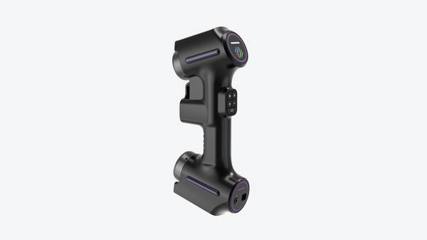
The deviation analysis is where structure matters most. Out-of-tolerance features get flagged with feature ID, deviation magnitude, and exact location attached. Not a color map someone has to interpret later — a workable exception record. A process engineer can open that record and see immediately whether the issue is a tool wear pattern, a fixturing shift, or something intermittent.
Production leads get the same context at the same time.
That shared context is what enables joint root-cause analysis before the next part runs. If a bore is drifting high on the Y-axis, the conversation stops being “quality rejected three parts” and becomes “the fixture clamp on station two has shifted 0.15 mm.” Tool wear adjustments and fixturing corrections happen while the line is still running, not after a batch of nonconforming parts has accumulated.
INSVISION 3D scanning solutions fit into existing quality management systems, pushing scan data directly into traceability workflows that plants already use for ISO and ASME compliance. That means the exception record doesn’t live in a separate scanner software silo — it lands in the same audit trail as CMM reports and manual inspection records.
For Western manufacturers supplying automotive, aerospace, or medical customers, that traceability is not optional. It’s part of the customer audit package.
The operational payoff is straightforward: less time cleaning and aligning scans, fewer ambiguous rejections, and faster closure on root cause. Quality teams spend their hours on engineering judgment, not data prep. Production gets actionable information before additional parts are produced.
And when an auditor asks to see the full history of a deviation, the record already exists in the system — feature ID, magnitude, location, and disposition.
Conformance Report Delivery and Standardized Reinspection Protocols
Most inspection programs treat the final report as the end of the job. That assumption quietly undermines process control. The scan gets completed, a deviation gets flagged, someone reviews the color map, and the data sits in a local folder. Weeks later, when a similar nonconformance appears at the customer’s incoming inspection, nobody can reconstruct what happened or why the corrective action failed to hold.
The final phase of a closed-loop 3D scanning workflow changes that. It treats report delivery and reinspection as operational controls, not administrative steps. For a Calibry 3D scanner deployed on a production line or in a quality lab, the value comes from turning raw scan data into a structured quality record that supports traceability, supplier communication, and repeatable verification.
Automated conformance reporting is the first piece. Instead of manually exporting screenshots or reformatting spreadsheets, the software generates ISO/ASME-compliant reports tied to the original GD&T callouts and tolerance bands. A quality engineer can send the same report to an internal machining cell, an external supplier, or an end customer without reworking the data.
That consistency matters when the part is an aerospace bracket with a true position tolerance or a medical device housing with a surface profile requirement. The report becomes the shared reference for disposition decisions.
Secure digital archiving is the second piece. Raw scan data, alignment history, and analysis results should be stored in a way that allows retrieval by part number, serial number, work order, or date range. Long-term traceability means that six months after a process change, the team can pull the original scan cloud and compare it against current production data. This is not just about passing an audit.
It supports root cause investigation when a recurring issue surfaces in the field or at a downstream operation.
The third piece is predefined reinspection triggers. These are the conditions that automatically prompt a follow-up scan. Common examples include post-tool-change verification, post-process-adjustment validation, or scheduled batch interval checks. If a CNC cell replaces an insert after roughing 40 housings, the next part gets scanned before it moves to finishing.
If a molding process adjusts pack pressure to fix sink marks, the first articles after the adjustment get verified against the master scan. These triggers prevent the typical drift where a corrective action gets implemented but never confirmed under production conditions.
INSVISION 3D scanning solutions support long-term trend analysis of scan data. That capability connects the final reporting phase back to lean manufacturing goals. Instead of treating each nonconformance as an isolated event, the quality team can review dimensional trends across batches and identify gradual tool wear, thermal drift, or fixture degradation before they produce out-of-tolerance parts.
The result is fewer disruptions to delivery cadence and less time spent on emergency rework.
From a cost perspective, the reporting and reinspection phase is where many factories lose the return on their measurement investment. A scanner that shortens inspection time but produces disconnected data files creates a different bottleneck: the quality engineer manually assembling reports, chasing revision history, and re-scanning parts because the original data was not archived properly.
Standardized protocols remove that hidden labor.
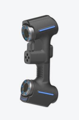
The practical implementation is straightforward. Start with one part family or one production cell. Define the conformance report template, the archive structure, and two or three reinspection triggers. Run the workflow for a month. Review how often the triggers fire and whether the resulting actions prevent downstream issues. That feedback loop is the point. Report delivery and reinspection are not the end of quality control.
They are the beginning of the next improvement cycle.
Hangzhou Insvision Technology Co., Ltd.
Address: Building 1, No. 1399 Liangmu Road, Yuhang District, Hangzhou, Zhejiang 311121, China
Copyright © Hangzhou Insvision Technology Co., Ltd. All rights reserved.
Copyright © Hangzhou Insvision Technology Co., Ltd. All rights reserved.