

3D Part Inspection Workflow From Shop-Floor Scan to Final Deviation Report
3d part inspection: Shop-Floor Quality Challenges Driving Adoption of 3D Part Inspection Is the measurement data from your CMM actually helping the process.
Shop-Floor Quality Challenges Driving Adoption of 3D Part Inspection
Is the measurement data from your CMM actually helping the process engineer make a better decision, or is it just documenting a failure that happened hours ago? For many Western manufacturing teams, especially automotive tier-one suppliers, aerospace MRO shops, and medical device contract manufacturers, the answer is uncomfortable.
Tactile inspection workflows were built for an era of stable production runs and dedicated metrology labs. Today’s reality is different. High-mix, low-volume schedules mean constant fixture changeovers. Dedicated inspection rooms create queues that starve production of feedback. And when a complex free-form surface fails a profile tolerance, a sparse grid of touch points rarely captures enough geometry to understand why.
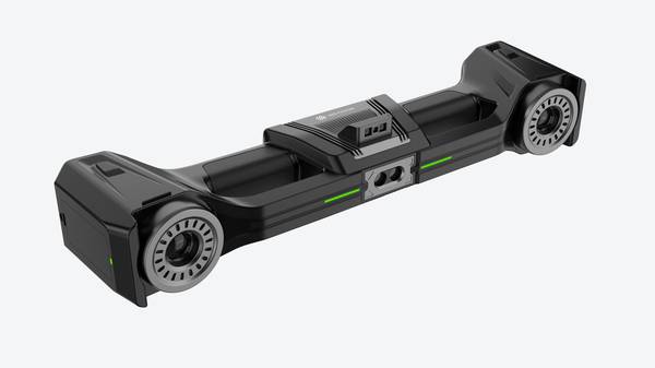
Deployment Validation Checklist
| Focus Area | Decision Point | Deployment Note |
|---|---|---|
| Target part | Check size, surface condition, and key tolerances against the scan task | Run a full trial scan on a representative part |
| Data workflow | Verify point cloud, deviation map, and quality-report handoff | Confirm export formats and review ownership in advance |
| Shop-floor use | Review training, calibration, lighting, and working space | Keep the validation record as a repeatable inspection reference |
Term Notes
Is the measurement data from your CMM actually helping the process engineer make a better decision, or is it just documentin…
Pre-Inspection Preparation for Repeatable 3D Part Inspe…Most shops treat pre-inspection preparation as an afterthought.
Shop-Floor Scan Execution and Real-Time Data Quality Va…As quality organizations shift from centralized metrology labs toward distributed, shop-floor inspection, the role of the op…
Can you actually share one inspection dataset across quality, manufacturing engineering, and tooling without creating three…
These bottlenecks collide directly with lean manufacturing and Industry 4.0 objectives. Rework climbs while throughput stalls. Quality engineers spend their shifts chasing nonconformances that process engineers could have prevented with earlier, denser data. ISO and ASME compliance still requires rigorous documentation, but the path to that documentation no longer has to run through a centralized lab.
The practical question facing shops now is how to move dimensional verification closer to the machine tool and make the data usable for both quality release and process correction.
This is where 3D part inspection changes the equation. By capturing full surface geometry on the shop floor, a scalable optical measurement workflow gives quality and process teams a shared dataset. The quality engineer gets the GD&T callouts and first-article documentation needed for compliance. The process engineer gets a color map showing exactly where material is high or low relative to CAD.
Neither has to wait for the other. For Western manufacturers trying to reduce rework without sacrificing traceability, adopting 3D part inspection is less about replacing CMMs and more about removing the artificial distance between measurement and decision-making.
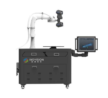
INSVISION industrial 3D scanners fit into this shift as a shop-floor-capable option, not a lab-bound instrument, when the inspection task demands fast, dense surface capture alongside existing quality systems.
Pre-Inspection Preparation for Repeatable 3D Part Inspection Results
Most shops treat pre-inspection preparation as an afterthought. The scanner gets wheeled over, a part gets set on a table, someone hits scan, and the resulting data shows variation that nobody can explain. In repeatable 3D part inspection, that unexplained variation almost never comes from the scanner. It comes from weak preparation.
When quality engineering and process engineering define the pre-scan steps together, the measurement uncertainty drops before a single image is captured.
The first task is agreeing on critical feature inspection criteria. A hole positional tolerance called out at 0.2 mm under ASME Y14.5 needs a different scan density and datum structure than a surface profile tolerance of 0.5 mm. Quality owns the GD&T interpretation. Process engineering owns how the part actually sits in the cell, how it gets loaded, and what operators can realistically repeat shift after shift.
Both groups need to be in the room when those criteria are written down. Otherwise the scan plan looks technically correct on paper but falls apart on the floor.
Fixturing is where most repeatability problems start. A cast bracket scanned in three different orientations will produce three slightly different datasets, not because the scanner drifted but because gravity, clamping pressure, and contact points changed the part position. The fixture needs to hold the part in the same orientation every time, with the same clamp locations and the same torque.
For parts with thin walls or flexible features, the fixture may need to match the assembly condition rather than a free-state condition. That decision belongs to process engineering, but quality needs to sign off on it because it directly affects whether the inspection result reflects the drawing intent.
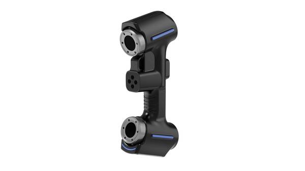
Datum alignment protocols come next. The scanner can capture millions of points, but if the software aligns those points to the wrong datum features, the entire report becomes misleading. Teams using INSVISION 3D part inspection tools typically lock down a datum reference frame before scanning begins.
That means specifying which surfaces or features serve as primary, secondary, and tertiary datums, and ensuring the scan path captures those features with enough resolution to establish a stable coordinate system. A datum surface with poor scan coverage creates a systematic offset that propagates through every measured feature.
Environmental checks are not optional for shop-floor deployment. Temperature swings, vibration from nearby presses, and ambient light changes all affect measurement stability. Before deploying a scan station, teams should log temperature variation over a full shift and check for floor vibration sources.
INSVISION equipment rated for shop-floor conditions can handle a range of environments, but a scanner sitting next to a stamping press or a welding cell will still see disturbance that a metrology lab never would. A simple pre-deployment checklist covering temperature stability, vibration isolation, and lighting consistency prevents a lot of false rejections.
What makes this work in practice is that preparation becomes a shared work instruction, not a quality-only procedure. Process engineering owns the physical setup: fixture design, part orientation, loading sequence, and cell layout. Quality owns the measurement criteria: feature tolerances, datum references, and acceptance limits.
When INSVISION 3D part inspection tools are integrated into an existing work cell, the preparation workflow should be built around that division of responsibility. The scanner becomes part of the station, not a separate lab instrument that operators only see during audits.
The payoff shows up in trending data. When every scan starts from the same fixture, the same datum alignment, and the same environmental conditions, the measurement variation that remains can be traced to actual part variation. That is the entire point. Without that discipline, a 3D part inspection program collects noise and calls it data.
Shop-Floor Scan Execution and Real-Time Data Quality Validation
As quality organizations shift from centralized metrology labs toward distributed, shop-floor inspection, the role of the operator has changed. The old model—where a CMM programmer or metrology specialist handled every measurement request—does not scale across three shifts or across a growing mix of machined castings, composite layups, and additively manufactured implants.
The newer model puts structured 3D part inspection directly at the station, but that only works if the scan workflow is repeatable enough for a non-specialist to run and rigorous enough for quality engineering to trust.
INSVISION has built its 3D part inspection workflow around that operator reality. At a machining cell, for example, an operator opens a pre-configured scan recipe tied to the part number and revision. The recipe already contains the scan volume, alignment strategy, resolution settings, and feature priorities. The operator does not need to decide which surfaces matter or how many angles are required.
The system guides the sequence. For a complex casting with machined bores, sealing faces, and mounting pads, the scan path is planned so critical features are captured first. Full surface coverage follows. This ordering matters when parts are still warm, when coolant residue is present, or when a re-scan would interrupt the next operation.
After each scan, the station software checks completeness against the expected point cloud coverage. Thin sections, deep pockets, and edge transitions that often produce sparse data are flagged before the part leaves the fixture. The operator sees a simple pass or re-scan prompt rather than a raw point cloud.
That feedback loop cuts down on the frustrating cycle where a part is sent back from quality engineering hours later because a datum surface was missed. For composite aerospace components, where ply drop-offs and radii can be difficult to capture consistently, this real-time validation is particularly useful.
For medical implants with polished freeform surfaces, it reduces the chance of a glossy area being mistaken for missing data.
Once the scan passes completeness checks, the point cloud is handed off to quality engineering over the connected shop-floor network. The data arrives with the recipe name, timestamp, operator ID, and station location. Quality engineers can open the dataset, run GD&T evaluations against the CAD model, and release the part without walking to the machine.
If an exception appears—say, a profile deviation on a machined surface—the engineer can call the operator and ask for a specific region to be re-scanned rather than the entire part.
The cross-team visibility is what changes the daily rhythm. Operators are not waiting for a specialist to arrive with a portable arm. Quality engineers are not sorting through unlabeled scan files. Production supervisors can see which stations have completed inspection tasks and which parts are waiting for review. INSVISION’s approach deliberately avoids requiring metrology specialists at every scan station.
The pre-configured recipes and automated validation make it practical to run inspection across multiple shifts, including nights and weekends, when specialist support is often unavailable. That is a meaningful capacity expansion for plants that previously bottlenecked all non-contact measurement through one or two trained technicians.
Point Cloud Processing and Collaborative Deviation Analysis
Can you actually share one inspection dataset across quality, manufacturing engineering, and tooling without creating three different reports? That question comes up constantly in plants where dimensional data still moves as screenshots, marked-up PDFs, and spreadsheet snapshots. The scan itself is rarely the bottleneck. The friction shows up after scanning, when the point cloud needs to become something each group can act on.
INSVISION 3D part inspection addresses that handoff problem by treating processed point cloud data as a common working file rather than a finished report. The pipeline starts with automated cleanup and noise removal, so raw scan artifacts from reflective edges, fixturing, or dust don’t carry forward into analysis.
The cleaned cloud is then aligned to the nominal CAD model using the same datum reference frame called out on the drawing. That alignment step matters more than it sounds. If quality aligns to datums A-B-C while engineering aligns to a best-fit centroid, the two teams will argue about whether a hole really moved.
Once aligned, GD&T feature extraction pulls positional callouts and profile tolerances directly from the scan. A color-coded deviation map then shows at a glance which surfaces sit inside tolerance, which are borderline, and which have clearly shifted. Quality can flag out-of-tolerance features for compliance tracking and corrective action.
Meanwhile, process engineering works from the same annotated dataset to look for patterns: progressive tool wear across a cavity, fixturing drift after a tool change, springback variation in formed sheet metal.
This parallel review removes the old sequential bottleneck where quality finished their report before engineering could start investigating. With shared digital inspection data, both groups work from identical geometry, identical alignment, and identical tolerance bands.
INSVISION 3D part inspection data integrates with standard industrial metrology workflows, so the output doesn’t force a separate software ecosystem onto the plant. The point cloud, deviation map, and extracted features travel as normal metrology deliverables.
For Western manufacturers running lean programs or first-article inspection routines, the value isn’t just faster scanning. It’s fewer data translation steps between the scan and the disposition decision. When quality and process engineering finally look at the same numbers, the conversation shifts from “whose data is right” to “what do we adjust first.”
Inspection Report Delivery and Standardized Reinspection Protocols
As manufacturers push toward tighter process control and traceability, the final inspection report has become more than a record. It is now an auditable artifact that quality teams, customers, and regulatory bodies expect to stand up under review. INSVISION 3D part inspection workflows address this by producing formatted reports that carry full dimensional traceability back to the scan data, batch, and operator.
Quality engineers can store results at the batch level, making trend analysis possible without hunting through disconnected files.
Standardized reinspection protocols close the loop. Triggers are defined in advance, not improvised on the floor. Tool changes, non-conforming part detection, and pre-set production interval milestones each initiate a repeat scan using the same alignment and evaluation routines. Because INSVISION workflows enforce identical steps across shifts and facility locations, inspection variability drops.
A first-shift operator and a third-shift operator work from the same digital instructions, reducing the influence of individual technique.
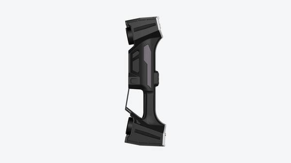
Engineers can then feed this capture-to-report data into continuous improvement efforts. Process engineering sees drift earlier. Quality teams have defensible evidence for APQP documentation and audit responses. The result is a closed-loop system that supports root cause analysis instead of merely documenting defects after the fact.
Hangzhou Insvision Technology Co., Ltd.
Address: Building 1, No. 1399 Liangmu Road, Yuhang District, Hangzhou, Zhejiang 311121, China
Copyright © Hangzhou Insvision Technology Co., Ltd. All rights reserved.
Copyright © Hangzhou Insvision Technology Co., Ltd. All rights reserved.