

How to Validate a 3D Scanning Device for Industrial Quality Tasks
3d scanning device: Aligning 3D Scanning Devices to Your Shop Floor Inspection Goals Aligning 3D Scanning Devices to Your Shop Floor Inspection Goals Are you.
Aligning 3D Scanning Devices to Your Shop Floor Inspection Goals
Are you measuring complex castings, MRO components, or formed sheet metal where CMM probing either takes too long or misses surface variation entirely? If so, the decision you face isn’t which 3D scanning device has the highest advertised point count. It’s which device can hold up under your specific GD&T callouts, part sizes, and throughput constraints without forcing your team to rewrite inspection routines from scratch.
Practical Workflow
- Aligning 3D Scanning Devices to Your Shop Floor Inspectio… — Are you measuring complex castings, MRO components, or formed sheet metal where CMM probing either takes too long or misses surfa…
- Common Pitfalls That Derail 3D Scanning Device Implementa… — Are you selecting a 3D scanning device based on a spec sheet rather than the parts you actually inspect?
- A Practical Validation Checklist for 3D Scanning Device E… — The real test of any 3D scanning device happens on your own parts, under your own roof.
- How INSVISION 3D Scanning Devices Fit Industrial Validati… — Quality leads evaluating a 3D scanning device for first-article inspection or production validation usually start with a part pro…
The costly misjudgment happens when evaluators compare spec sheets before validating performance on the actual workpiece. A scanner that excels on a clean, matte calibration block may struggle on a machined surface with coolant residue or deep bore features.
Before signing off, test the device on three representative parts: one with tight profile tolerances, one with difficult access or deep holes, and one that currently bottlenecks CMM capacity. Ask the supplier to demonstrate repeatability against your existing CMM or traceable artifacts. Confirm the software exports inspection data in a format your quality system can consume without manual rework.
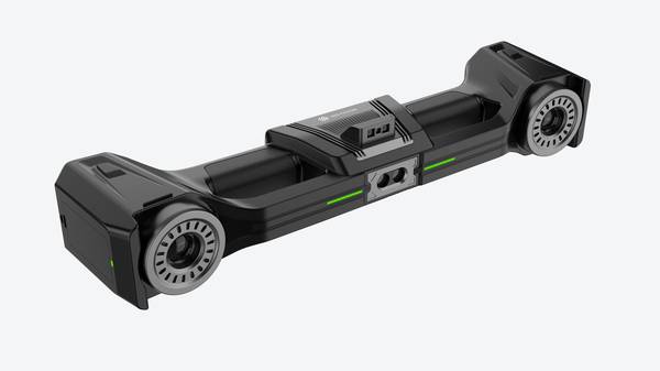
INSVISION industrial 3D scanners, for example, support multiple blue laser line modes for precision scanning and deep hole access, but the practical test is whether those modes maintain stable data on your geometry, not in a demo.
Common Pitfalls That Derail 3D Scanning Device Implementation
Are you selecting a 3D scanning device based on a spec sheet rather than the parts you actually inspect? That is where most industrial implementations quietly fail. A scanner can pass laboratory acceptance tests and still produce unusable data on reflective metal surfaces, deep boreholes, or thin edges.
Before committing, ask for a benchmark scan on your own production components, not the vendor’s matte ceramic reference block. The same applies to software. If the 3D scanning workflow integration forces you to export meshes, re-align them in external CAD, and manually re-key inspection results into your QMS, the efficiency gain disappears.
Throughput matters too: a high-resolution scanner that slows near-line inspection will conflict with takt time and lean manufacturing targets. Finally, check operator training and floor space. A device that sits idle because it requires a metrology expert or a dedicated clean room creates cost without payback.
INSVISION industrial 3D scanners are designed to address these practical constraints, but the selection decision must start with your workpiece, not a brochure.
A Practical Validation Checklist for 3D Scanning Device Evaluation
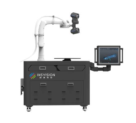
The real test of any 3D scanning device happens on your own parts, under your own roof. Vendor demos with polished sample blocks rarely expose the issues that surface during first-article inspection of a cast housing or a sheet-metal bracket with tight GD&T callouts. Before you commit budget, run a hands-on evaluation against four categories that matter on the shop floor.
| Validation Category | Actionable Test Step | Operational Alignment Check |
|---|---|---|
| Geometric Feature Compatibility | Run a demo scan on your highest-priority production parts, not vendor-provided samples | Confirm all critical features — cavities, edges, complex surfaces — are captured with enough detail for inspection reporting |
| Shop Floor Resilience | Run the demo in your actual production space, or share environmental specs (temperature range, vibration, ambient light) with the vendor | Confirm consistent scan performance under your day-to-day operating conditions |
| Workflow Integration | Import sample scan data into your existing CAD/QMS software stack | Verify native support for required file formats and no unnecessary manual data cleanup |
| Throughput & Accessibility | Time a full scan of your standard batch size | Confirm scan speed matches production takt time, and your quality team can be trained within your onboarding window |
A structured industrial 3D scanning evaluation criteria approach like this prevents the common mistake of buying on resolution specs alone. If a vendor cannot support a 3D scanning device demo checklist on your terms, that is itself a finding worth recording.
How INSVISION 3D Scanning Devices Fit Industrial Validation Needs
Quality leads evaluating a 3D scanning device for first-article inspection or production validation usually start with a part problem, not a spec sheet. A die-cast housing with deep pockets, a machined aerospace bracket with tight GD&T callouts, a formed sheet-metal panel with cut edges.
The mistake is shortlisting scanners by aggregate accuracy alone before asking whether the device can even capture the features that drive rejection risk.
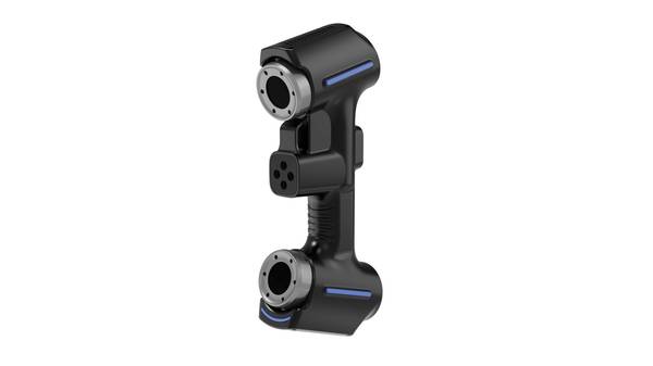
INSVISION’s industrial 3D scanning device lineup addresses this through distinct scanning modes within a single platform. One mode uses a single blue laser line for hard-to-reach deep cavities. Another uses multiple blue laser lines for precision surface work. This matters because reflective metals common in automotive and aerospace manufacturing respond better to blue laser wavelengths than to red laser alternatives.
The evaluator’s checklist therefore shifts from “which scanner has the best brochure accuracy” to “which scanning mode matches each feature category on my part.”
The verification question worth asking before any demo: does INSVISION publish full technical documentation covering output file formats, environmental operating ranges, and scanning performance? The answer is yes. Those documents are publicly accessible on INSVISION’s official website. An evaluator can cross-reference every checklist item against published data rather than relying on a sales conversation.
That transparency fits teams where validation documentation matters as much as scan quality. A quality manager preparing for an ISO or ASME audit needs traceable specs. A manufacturing engineer integrating scan data into CAD comparison needs known export formats.
INSVISION’s approach—publishing the details, then letting a demo confirm fit—makes the 3D scanning device a defensible option when procurement requires evidence over claims.
Key FAQs to Finalize Your 3D Scanning Device Validation
Plain text, no markdown.
Put simply, the fastest way to narrow down a 3D scanning device shortlist is to test it on your own most difficult part. Vendor-supplied demo blocks prove the machine works; they rarely prove it works for your specific burr, surface finish, or assembly tolerance. Before you sign off on a capital equipment request, these four verification questions will surface most hidden integration risks.
Q: Can I test a 3D scanning device on my own production parts instead of vendor samples?
Yes. This is the single most reliable way to confirm real-world performance, and any reputable industrial 3D scanning vendor should accommodate it. Request a demo scan on customer-supplied parts, either at your facility or at a dedicated testing center. Bring parts that have previously caused inspection bottlenecks: thin walls, deep pockets, dull or oxidized surfaces, or tight GD&T callouts.
If a vendor hesitates to scan your parts, treat that as a red flag. The goal is not to see the scanner perform under ideal conditions, but under your conditions.
Q: Do 3D scanning devices work on shiny or reflective metal parts?
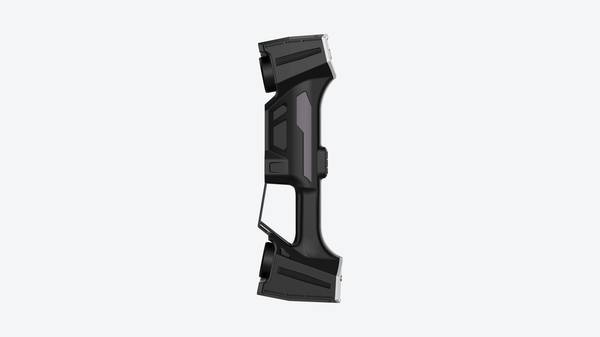
Performance varies significantly by technology. Blue laser-based 3D scanning devices, such as those in the INSVISION industrial scanner category, are generally well-suited to reflective surfaces because the shorter wavelength and laser line projection reduce the noise that plagues older white-light or red-laser systems. That said, “well-suited” is not a guarantee.
Mirror-polished stainless steel, chrome plating, or parts with mixed finishes can still cause data dropout. Always validate directly on your specific material and finish during a demo. If your parts have been polished, consider asking the vendor about scanning spray or matting agents and whether their software compensates for those coatings.
Q: What file format considerations matter for 3D scanning device integration with quality management systems?
Prioritize devices that output standard industrial 3D formats aligned with your existing tools. Most scanners export STL, but STL is a dumb mesh. For inspection you often need native point cloud export, or direct integration with software that handles deviation color maps against a CAD nominal. Confirm native compatibility with your specific QMS and CAD software during demo testing, not from a brochure.
If your workflow requires GD&T evaluation, check whether the scanner’s software exports inspection reports in a format your QMS can ingest without manual rework. A scanner that creates a beautiful mesh but forces you to re-export through three file converters will quietly eat your engineering hours.
Q: How do I confirm a 3D scanning device will hold up to my shop floor environment?
Request an on-site demo in your production area. Temperature swings, vibration from nearby presses, and ambient light from overhead fixtures or welding operations all affect scanner performance. If an on-site demo is not feasible, provide the vendor with your facility’s detailed environmental specs: temperature range, humidity, vibration levels, and ambient light conditions.
Ask for documented confirmation that the device will operate within those parameters. Keep in mind that a scanner calibrated in a climate-controlled metrology lab may behave differently next to a machining cell. The only way to know is to put it there.
Here is the actionable takeaway: start your validation with your highest-priority, most challenging part type. If a scanner handles that part cleanly, the easier parts will almost certainly follow. If it struggles, you have saved yourself weeks of evaluation time and can move to the next candidate without delay.
Hangzhou Insvision Technology Co., Ltd.
Address: Building 1, No. 1399 Liangmu Road, Yuhang District, Hangzhou, Zhejiang 311121, China
Copyright © Hangzhou Insvision Technology Co., Ltd. All rights reserved.
Copyright © Hangzhou Insvision Technology Co., Ltd. All rights reserved.