

Why 3D Scan Parts for Precision Inspection Need Upfront Application Diagnostics
3d scan parts: The Hidden Operational Costs of Misaligned 3D Scan Parts Workflows Most teams assume a 3D scan parts workflow fails because the scanner lacks.
The Hidden Operational Costs of Misaligned 3D Scan Parts Workflows
Most teams assume a 3D scan parts workflow fails because the scanner lacks resolution. In practice, the expensive failures happen earlier—before anyone picks up the sensor.
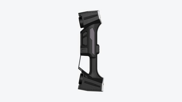
Practical Workflow
- The Hidden Operational Costs of Misaligned 3D Scan Parts… — Most teams assume a 3D scan parts workflow fails because the scanner lacks resolution.
- Core Application Constraints to Diagnose Before Selecting… — Most failed 3D scanning deployments are not caused by bad hardware.
- Common Capture and Alignment Risks That Erode 3D Scan Par… — The assumption that a 3D scanner solves inspection problems simply by capturing more points faster is one of the more expensive m…
- How INSVISION Approaches 3D Scan Parts Fit for Operationa… — Shops that used to accept a day or two for first-article inspection now face shorter lead times and tighter GD&T callouts.
A solution engineer sees the same pattern across aerospace MRO, automotive OEM, and medical device work. A turbine blade comes in for inspection. Someone scans it without mapping the leading-edge radii to the GD&T callouts first. The mesh looks complete, but the alignment drifts. The first-article report shows out-of-tolerance zones where none exist. Quality rejects the job.
Deployment Validation Checklist
| Focus Area | Decision Point | Deployment Note |
|---|---|---|
| Target part | Check size, surface condition, and key tolerances against the scan task | Run a full trial scan on a representative part |
| Data workflow | Verify point cloud, deviation map, and quality-report handoff | Confirm export formats and review ownership in advance |
| Shop-floor use | Review training, calibration, lighting, and working space | Keep the validation record as a repeatable inspection reference |
The part goes back for rework, then rescan, then manual CMM verification.
The hidden cost is not the scanner. It is the absence of a task-first diagnostic. Without defining capture constraints, alignment references, rescan triggers, and validation criteria against ISO 10360 or ASME Y14.5, teams burn hours repeating scans and chasing false deviations.
INSVISION industrial 3D scanning equipment supports this diagnostic approach, but the operational value comes from sequence: define the inspection intent, constrain the scan, validate the alignment, then release the data. Skip that, and the downstream costs compound quietly.
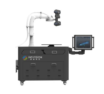
Core Application Constraints to Diagnose Before Selecting a Scanning System
Most failed 3D scanning deployments are not caused by bad hardware. They are caused by a mismatch between six application constraints and the system selected to handle them. A solution engineer should walk through these six dimensions before any purchase decision, because each one affects long-term efficiency, rework, and total cost of ownership. Skip one, and you either buy too much scanner or too little.
Part material and surface properties come first. Reflective carbon fiber aerospace components, matte medical polymer parts, and machined metal automotive parts all interact with structured light or laser scanning differently. A reflective surface can create noise that forces rescanning or manual cleanup. A matte polymer may scan easily but require different exposure settings.
If the system cannot handle your dominant surface type without heavy operator intervention, throughput suffers quietly over months.
Part geometry is equally decisive. Deep-cavity hydraulic valves block line of sight. Free-form turbine blades demand high point density across curved surfaces. Flat stamped sheet metal presents the opposite problem: too little geometric texture for reliable alignment. Each geometry stresses a different part of the scanning system.
A solution that excels on turbine blades may struggle with deep cavities, and the only way to know is to test with your actual parts, not demo blocks.
Tolerance requirements separate convenience tools from inspection-grade systems. Micron-level medical implant checks require validated accuracy and repeatability, not just visual fidelity. Heavy equipment weldment verification tolerates looser numbers but demands stable performance over large volumes. Buying a high-accuracy system for loose-tolerance work overspends.
Buying a low-accuracy system for tight GD&T callouts creates rework and customer rejections.
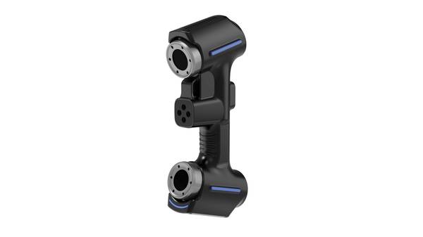
Operating environment is the constraint most buyers ignore until after installation. Climate-controlled quality labs are forgiving. Dust-prone shop floors and variable-temperature production areas are not. Temperature swings affect dimensional stability of both the scanner and the part. Dust degrades optics and calibration.
INSVISION systems are engineered for industrial conditions, but the specific environment still dictates enclosure needs, calibration frequency, and operator workflow.
Takt time and throughput needs determine whether you need in-line 100% inspection, near-line batch sampling, or offline full inspection. In-line inspection at production cadence demands automation and fast data capture. Offline inspection tolerates longer cycle times but shifts labor cost upstream. Misjudging this dimension means either a bottleneck at the scanner or an expensive automated system sitting idle half the shift.
Required data deliverables affect software, not just hardware. CAD comparison reports, mesh files, and quality traceability records each require different post-processing workflows. Traceability records for ISO or ASME compliance add database and reporting overhead. If your scanning system cannot output the right deliverable without manual reformatting, the hidden labor cost erases any hardware savings.
No single scanner solves all six constraints optimally. The diagnostic framework forces you to rank them honestly. INSVISION application engineers use this same structure to de-risk 3D scan parts projects before quoting, because the most expensive mistake is discovering a constraint mismatch after the system is on your floor.
Common Capture and Alignment Risks That Erode 3D Scan Parts ROI
The assumption that a 3D scanner solves inspection problems simply by capturing more points faster is one of the more expensive misconceptions I run into on the plant floor. The hardware is rarely the constraint.
The failure points sit upstream and downstream of the scan itself: how the part is referenced, what the scanner actually sees, whether the setup can be repeated by a second-shift operator, and what happens to the data after capture. When those elements are under-diagnosed, the expected return on 3D scan parts investment quietly erodes.
What looked like a labor-saving quality tool becomes another source of rework, schedule slippage, and audit exposure.
Misaligned part reference frames are the most common root cause I see. An operator aligns a scan to the wrong datum structure, or the alignment drifts because the part was not fixtured the same way between capture sessions. The scanner then reports deviation where none exists. A good machined feature gets flagged as non-conforming.
The result is wasted rework on parts that were never out of tolerance, plus the slower, more damaging consequence: inspectors begin to distrust the measurement data. Once that trust erodes, they start double-checking scans manually, and the efficiency gain you bought the scanner to achieve is gone.
Insufficient coverage for hidden or undercut features creates a different kind of cost. A single scan path may capture the visible surfaces cleanly while missing pockets, deep bores, or flange undersides. The operator discovers the gap during downstream CAD comparison, then has to break down the setup, reposition the part, and rescan. On a busy inspection bench, that is not a five-minute correction.
It bottlenecks the workflow, delays first-article approval, and creates pressure to release parts with incomplete data rather than hold the schedule. I have seen this pattern turn a supposedly fast scanning station into a queuing problem.
Poor repeatability from unvalidated setups is quieter but just as damaging. If the fixture, scan path, and alignment routine are not documented and verified, two operators can produce two different results from the same part. That undermines quality traceability. In an ISO or ASME audit context, the question is not whether the scanner is accurate; it is whether the measurement process is reproducible.
A scanner with a strong accuracy specification does not help if the process around it cannot survive a shift change or a re-qualification review. Audit findings, corrective action requests, and customer confidence all take a hit.
Data format and workflow mismatches are the last common failure point, and they are often underestimated at purchase time. The scan output may not flow cleanly into the CAD comparison software, the MES database, or the reporting template the quality team already uses. Engineers end up manually converting files, re-exporting meshes, or rebuilding reports.
That hidden labor costs more than most teams admit because it does not show up on the scanner’s cycle time. It shows up in engineering hours, delayed PPAP submissions, and a growing sense that the system is more trouble than it is worth.
These risks compound. A misaligned reference frame triggers a false non-conformance. The false non-conformance leads to unnecessary rework. The rework consumes capacity that should have gone to real production issues. Meanwhile, the rescan bottleneck from poor coverage delays the next inspection job, and the data mismatch slows reporting. Over time, the total cost of ownership rises well beyond the initial equipment purchase.
The scanner itself may be fine; the deployment around it is what determines whether 3D scan parts initiatives deliver operating value or become another underutilized asset on the quality bench. INSVISION equipment, when deployed with attention to reference strategy, coverage planning, and downstream data flow, can avoid many of these traps, but the process discipline matters as much as the hardware.
How INSVISION Approaches 3D Scan Parts Fit for Operational Success
Shops that used to accept a day or two for first-article inspection now face shorter lead times and tighter GD&T callouts. That shift changes what a 3D scan parts deployment has to deliver. INSVISION starts from the constraint side, not the spec sheet. The first question is what the part and the process actually demand.
A large cast housing checked near the line has different requirements than a small machined component verified in a lab. Environment matters too. Temperature swings, dust, vibration, and operator skill all affect repeatability. So does throughput. If inspection lags production, the scanner becomes a bottleneck instead of a quality gate.
INSVISION works with engineering, quality, and operations to define capture, alignment, rescan, and validation steps before recommending hardware. That means validating part size, surface finish, required data deliverables, and how results flow into existing quality systems. Matching capability to the task avoids paying for precision you cannot use or buying speed that cannot hold tolerance.
A Practical Validation Checklist for 3D Scan Parts Deployment Success
Are you certain the scan data you are collecting will hold up when the production line is running at full speed? Many teams validate a 3D scan parts solution on a single reference block and call it done, then discover alignment drift or software conflicts weeks later. That approach creates expensive surprises.
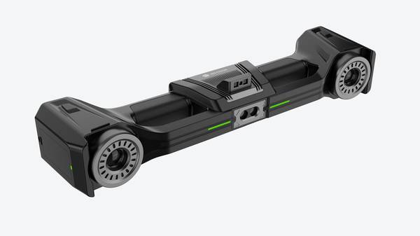
The checklist below covers five areas worth testing before you commit. First, check capture repeatability across a representative set of production parts, not just one clean sample. Include the material and geometry variations your operators see daily. Second, verify alignment accuracy against calibrated reference artifacts tied to ISO or ASME metrology standards.
Third, run the scanner in the actual deployment location to confirm environmental resilience under real lighting, vibration, and temperature conditions. Fourth, test compatibility with your existing quality software, production databases, and required output formats. Fifth, measure inspection cycle time against takt time for both routine and high-volume runs. If any area fails, fix it before rollout.
Hangzhou Insvision Technology Co., Ltd.
Address: Building 1, No. 1399 Liangmu Road, Yuhang District, Hangzhou, Zhejiang 311121, China
Copyright © Hangzhou Insvision Technology Co., Ltd. All rights reserved.
Copyright © Hangzhou Insvision Technology Co., Ltd. All rights reserved.