

Key Verification Steps for 3D Scanning Machines Before Full Deployment
3d scanning machines: Hidden Implementation Risks of 3D Scanning Machines in Quality Workflows Hidden Implementation Risks of 3D Scanning Machines in Quality.
Hidden Implementation Risks of 3D Scanning Machines in Quality Workflows
A quality engineer at an aerospace MRO facility unpacks a new 3D scanning machine, powers it on, and runs the vendor’s demo part. The point cloud looks clean. Cycle time appears fast. Then the real work begins: importing legacy CAD nominals, aligning scan data to ASME Y14.5 GD&T callouts, validating against the facility’s ISO 9001 inspection SOPs, and passing the results through a first-article inspection package.
This is where off-the-shelf performance claims often collide with production reality.
Deployment Validation Checklist
| Focus Area | Decision Point | Deployment Note |
|---|---|---|
| Target part | Check size, surface condition, and key tolerances against the scan task | Run a full trial scan on a representative part |
| Data workflow | Verify point cloud, deviation map, and quality-report handoff | Confirm export formats and review ownership in advance |
| Shop-floor use | Review training, calibration, lighting, and working space | Keep the validation record as a repeatable inspection reference |
Key Points at a Glance
- A quality engineer at an aerospace MRO facility unpacks a new 3D scanning machine, powers it on, and runs the vendor’s demo part.
- The most important step in adopting any industrial 3D scanning machine is not the demo.
- It is easy to assume that introducing 3D scanning machines into a mature production line means halting output, retraining everyone, and rewritin…
- Most Western manufacturers already know the pain: the CMM room has a backlog, the senior metrologist is stretched across three programs, and a l…
The gaps are rarely hardware flaws. More often, they are workflow integration failures. A scanner that excels in a lab demo may struggle to hold pace with a lean production cadence on the shop floor. Data export formats may not match the quality team’s existing metrology software.
Deep-hole scanning modes that work well on a clean bench sample may produce inconsistent results on a worn turbine component with mixed surface finishes. Medical device manufacturers face additional pressure when scan data must support traceable inspection records without adding manual steps.
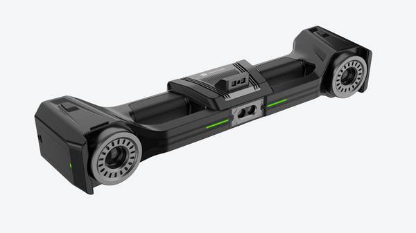
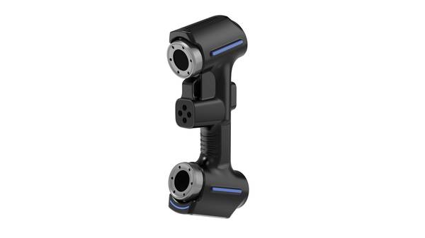
INSVISION equipment addresses some of these risks through practical scanning modes. For example, the industrial 3D scanner platform offers precision scanning with seven blue laser lines and a single-line deep-hole scanning mode, with scanning areas up to 650mm by 550mm. The industrial 3D scanner Elite S1 adds high-speed scanning with 50 blue laser lines and intelligent hole rescanning.
These capabilities matter less as specification sheet bullet points and more as workflow enablers: a quality team can switch between high-speed surface capture and targeted deep-hole inspection without swapping systems or rebuilding fixtures.
The real hidden risks sit in delivery timelines, not hardware. A Western automotive OEM evaluating 3D scanning machines typically needs confirmation that scan data integrates with existing SPC dashboards and CMM comparison routines. An energy sector supplier may require validation that the scanner can operate reliably in a non-climate-controlled inspection cell. None of these requirements show up on a standard spec sheet.
Pre-deployment verification — running the scanner against real parts, real tolerances, and real SOPs — is the only reliable way to avoid a six-week implementation delay turning into a six-month integration project.
Sample-Based Validation to Align 3D Scanning Machines With Production Needs
The most important step in adopting any industrial 3D scanning machine is not the demo. It is the sample validation. You need to see how the system behaves on your parts, with your tolerances, under conditions that resemble your inspection workflow. A structured sample-based validation removes most of the purchasing risk and gives engineering and quality teams a common set of evidence before capital approval.
Start by selecting parts that represent the difficult end of your production envelope. Deep holes, thin walls, curved aerospace skins, or small medical device features will expose weaknesses that flat calibration blocks never reveal. For deep holes, specify a scanning mode that uses a single blue laser line. Multi-line modes tend to lose data inside narrow cavities.
For larger surfaces, a mode with more laser lines can speed up acquisition, but the validation should confirm that speed does not degrade edge definition or hole recognition.
Consistency matters as much as absolute accuracy. Scan the same part three to five times, ideally on different shifts or after repositioning. Compare the point clouds and extracted features. If the repeated results drift beyond your tolerance band, the system may be sensitive to ambient temperature, operator technique, or part fixturing. That instability will show up later as rework or disputed measurements.
Tolerance alignment is the third test block. Take the GD&T callouts that already drive your inspection reports: profile, position, runout, flatness. Export the scanned data into the same software you use for CMM or comparator analysis. If the workflow cannot produce a clean comparison against those callouts, the scanner becomes a separate data island. That breaks traceability and adds labor.
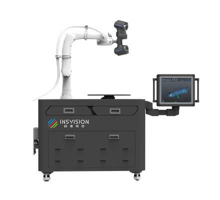
INSVISION supports pre-purchase sample scanning precisely for this reason. Instead of evaluating a generic demo block, you send production parts or representative part families. The goal is to confirm that the system fits existing inspection requirements, not to prove that it works on ideal geometry.
This is especially useful for aerospace MRO shops dealing with curved surfaces, or medical device manufacturers where small features and tight profiles dominate.
Document everything. Record the part number, material, surface finish, fixture setup, scan mode, number of passes, and the tolerance threshold for each feature. Add screenshots of deviation maps and any failed areas. That record serves two purposes. First, it gives internal stakeholders a factual basis for the purchase decision.
Second, it becomes an attachment for quality compliance audits, showing that the equipment was validated on real production parts before deployment.
A disciplined sample validation usually takes a few days. It costs far less than discovering after installation that the scanner cannot handle a critical part family. For teams looking to integrate 3D scanning machines into an existing quality workflow, that evidence is the difference between a tool that gets used daily and one that sits on a shelf.
Integrating 3D Scanning Machines Into Existing Quality Systems
It is easy to assume that introducing 3D scanning machines into a mature production line means halting output, retraining everyone, and rewriting your quality manual. In practice, the opposite tends to be true when the integration is scoped around the data you already need to ship product.
The first checkpoint is CAD and quality management software compatibility. If your engineering team lives in native CAD environments, the scanner output should arrive as clean geometry, not a proprietary mesh that requires hours of repair. The same applies to inspection reporting.
A scanner that cannot export a structured AS9102 or PPAP-friendly report without manual rekeying will quietly erode the efficiency you intended to gain.
The second checkpoint is data flow into MES and SPC systems. Real-time quality trend tracking only works when dimensional deviations are captured as structured values, not screenshot overlays. INSVISION works directly with client engineering and quality teams to map current inspection SOPs. The goal is not to replace the work cell layout or disrupt cycle time targets.
It is to place the scanner where the first-article or in-process check already happens, then adjust the workflow around existing part handling, datum alignment, and release gates.
For lean manufacturing lines, this means the scanner should fit the takt time, not the other way around. If a critical feature takes six minutes to inspect today, the scanner configuration should support that cadence while also capturing a fuller digital record. That record becomes the long-term value: traceable geometry tied to serial numbers, lot codes, and process shifts.
When a customer audit asks for dimensional history, you pull the dataset instead of searching through paper reports.
The operational logic is straightforward. Embed the scanner at the point of measurement you already trust, connect it to the systems you already use, and let the richer data reduce downstream sorting, dispute resolution, and rework. That is how 3D scanning machines become part of an existing quality workflow without an overhaul.
Structured Training and Post-Deployment Performance Reviews
Most Western manufacturers already know the pain: the CMM room has a backlog, the senior metrologist is stretched across three programs, and a line technician found a dimensional issue two hours after the shift started. The measurement equipment itself is rarely the bottleneck. The shortage of people who can run it consistently is.
That gap is what drives interest in 3D scanning machines. The hardware is faster than touch probing on complex surfaces, but speed only matters if the operator understands scan path planning, alignment, and when a mesh deviation map actually reflects a real GD&T callout. Without that understanding, two operators on different shifts can produce two different inspection reports from the same part.
That inconsistency creates rework, supplier disputes, and audit exposure.
INSVISION approaches this as a workforce problem rather than a tooling problem. The training structure follows three tiers. Tier one gets frontline quality technicians to a repeatable baseline: fixture the part, run the scan routine, verify the alignment, and export the report. These technicians do not need to become metrology engineers. They need to execute a defined workflow the same way at 6 a.m. and 6 p.m.
Tier two covers quality engineers who interpret the data, set pass/fail thresholds, and integrate scan results with existing inspection documentation. Tier three builds internal capability for system administration, so the plant is not dependent on outside support for routine maintenance, software updates, or network configuration changes.
The operational benefit shows up in shift-to-shift consistency. When a quality manager can trust that the first-article report from the night shift used the same scan parameters and alignment strategy as the day shift, the review cycle shortens. Measurement errors that used to trigger rework or suspect material holds become easier to catch at the source.
And when a customer audit asks for dimensional traceability, the plant can show a controlled process instead of relying on one skilled inspector’s personal technique.
Post-deployment reviews matter as much as initial training. Production mix changes, new part numbers enter the queue, and the original scan routine may no longer fit. INSVISION conducts structured review sessions after deployment to check whether the system is being used to its full capability.
Often the scanner is doing first-article work but not being used for in-process checks, or the team has not applied a scanning mode that would better suit a new surface geometry. These reviews also surface workflow friction that training alone does not fix, such as file naming conventions, data storage locations, or export formats that do not match the ERP or QMS system.
The payback is not just labor savings. It is reduced rework from measurement ambiguity, faster containment when a dimensional drift occurs, and cleaner traceability for customer audits. Fewer parts get scrapped or reworked because two inspectors disagreed on a surface profile measurement.
That is the kind of operational improvement a plant controller can see in the monthly P&L, even if it never appears on a scanner specification sheet.
Scaling 3D Scanning Workflows Across Production Operations
A lot of plants start with one scanner, one bench, and one engineer who becomes the internal expert. That works for a while. Then the first-article jobs pile up, another line starts asking for dimensional reports, and a customer audit introduces new traceability requirements.
The question stops being whether 3D scanning machines add value and becomes how to scale them across part families, shifts, and facilities without turning quality control into a bottleneck.
Before adding more equipment, the first step is identifying where scanning actually changes the workflow. Three conditions usually justify expansion. First, standardized part inspection requirements. If the same GD&T callouts, datum schemes, and report formats repeat across a product family, scanning can be templated rather than treated as a new setup each time.
Second, high-volume production lines with existing rework or inspection bottlenecks. A CMM queue that delays shipment by a day, or a manual gauge check that misses form error, creates recurring cost that scanning can often compress. Third, customer-mandated quality traceability rules.
When an OEM or aerospace buyer requires archived dimensional data for every batch, scanning moves from a nice-to-have tool into a production requirement.
The operational hurdle is setup time. Adding a new part number to the scanning workflow traditionally means rebuilding scan paths, inspection criteria, and report layouts from scratch. If each new part takes two days to configure, expanding beyond low-volume, high-complexity jobs feels expensive. That is where reusable scan templates and report frameworks matter.
A quality engineer should be able to load a template for a bracket or a machined housing, align the scan region, and generate a comparable report without redoing the entire workflow. INSVISION supports this by enabling teams to build scan templates that standardize how parts are oriented, which features are extracted, and how reports are structured. That reduces the practical cost of adding new part numbers to the system.
Standardized scan data also does something else. When multiple facilities measure the same part family using the same scan templates, the output becomes comparable across sites. A plant in one region can benchmark its process capability against another plant producing the same component.
This supports cross-facility quality benchmarking and aligns with ISO 9001 continuous improvement requirements, where evidence of consistent measurement and corrective action is expected during audits. Without standardized data, each site measures differently, and the comparison falls apart.
The trajectory that works for many operations is to start with the hardest parts, the ones where form error, surface profile, or hole position drives rework and customer complaints. Once the scan templates and report formats stabilize, the workflow extends to simpler parts that were previously inspected with hand tools. High-volume parts follow, especially where inspection queues or rework loops create visible delays.
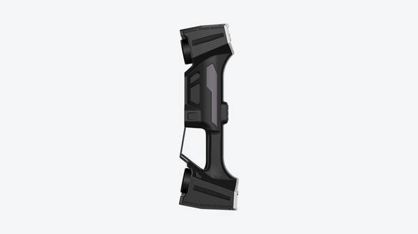
The scanner itself matters less than the repeatability of the process around it. INSVISION equipment supports scanning areas up to 650mm by 550mm on industrial 3D scanner-class systems and larger field-of-view options on industrial 3D scanner, but the scaling logic is about process design: template the inspection, standardize the report, and only then add equipment or stations.
For a Western manufacturing environment, this conversation usually starts with a quality manager or a production engineer who is tired of explaining CMM backlogs. The cost logic is not complicated. If scanning reduces the time from part production to dimensional confirmation, the line moves faster. If the scan report catches a drift in process capability before parts ship, rework and customer returns drop.
If the archived data satisfies a customer audit without a week of manual documentation, that is direct labor recovered. None of these require a dramatic digital transformation story. They require one repeatable workflow that can be copied across part numbers and plants.
The expansion path for 3D scanning machines across production operations therefore comes down to three questions. Which part families share inspection criteria that can be templated? Which lines currently lose time to inspection queues or rework loops? Which customers or standards require archived dimensional evidence? Answer those, and the scaling decision becomes an operational one, not a technology one.
Hangzhou Insvision Technology Co., Ltd.
Address: Building 1, No. 1399 Liangmu Road, Yuhang District, Hangzhou, Zhejiang 311121, China
Copyright © Hangzhou Insvision Technology Co., Ltd. All rights reserved.
Copyright © Hangzhou Insvision Technology Co., Ltd. All rights reserved.