

What to Validate When Evaluating Scanner Measurement for Precision Parts
Your Core Task: Vetting Scanner Measurement for Precision Part QC Are you certain the scanner measurement system you are evaluating can hold tolerance on the.
Your Core Task: Vetting Scanner Measurement for Precision Part QC
Are you certain the scanner measurement system you are evaluating can hold tolerance on the actual parts your line produces every day? Quality managers and manufacturing engineers in automotive OEM, aerospace MRO, and medical device facilities often miss this.
The most common misjudgment is buying on datasheet speed or accuracy alone, then discovering the system struggles with shiny machined surfaces, deep bores, or thin-wall edges under real shop lighting.
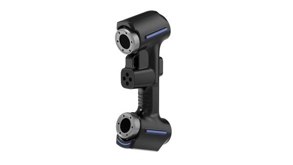
Scenario Snapshot
A practical way to read the article is through this scenario:
- Your Core Task: Vetting Scanner Measurement for Pre…: Are you certain the scanner measurement system you are evaluating can hold tolerance on the actual parts your line…
- Common Gaps That Derail Scanner Measurement Impleme…: Most scanner measurement evaluations miss the real failure points until equipment is already on the floor.
- Non-Negotiable Validation Criteria for Scanner Meas…: When a quality team evaluates scanner measurement for production inspection, the decision usually fails long befor…
Your core task is to vet scanner measurement against your specific part geometries, production cadence, and ISO/ASME compliance requirements. Start with first-article inspection: pull three known parts, including one with tight GD&T callouts like true position or profile of a surface. Run the scan, compare against your CMM baseline, and watch for deviation at edges and deep features.
Check cycle time at the line, not in a demo lab. Ask how the workflow handles fixture movement, ambient vibration, and operator variability. Confirm the software exports the exact report format your quality system needs.
INSVISION industrial 3D scanners offer high measurement rates across their current portfolio, but the deciding factor is not the spec sheet. It is whether the scanner measurement repeatability and scan-to-report workflow hold up on your worst-case part, not your easiest one.
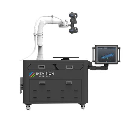
Common Gaps That Derail Scanner Measurement Implementation
Most scanner measurement evaluations miss the real failure points until equipment is already on the floor. The issue is rarely the scanner’s published accuracy. It is how the system behaves against specific part geometries, surface finishes, and the existing quality workflow. Four gaps consistently derail implementation in Western manufacturing environments, and each deserves scrutiny before a purchase decision.
The first gap is measurement repeatability on difficult surfaces. Aerospace and medical components frequently combine reflective machined faces, translucent polymers, and deep undercuts. A scanner that performs well on a matte calibration artifact can produce noisy or inconsistent data when operators move to a polished titanium bracket or a glass-filled polymer housing. During evaluation, do not rely on a vendor demo part.
Run the scanner against your own worst-case geometry and ask for repeated scans of the same feature. Check whether the system returns stable results without manual rework or operator-dependent alignment tricks.
The second gap is setup time in high-mix, low-volume production. Many Western job shops and aerospace suppliers change part numbers multiple times per shift. If the scanner requires frequent recalibration, lengthy fixture setup, or extensive target placement, the measured cycle time on a single part becomes irrelevant. The real metric is floor-to-floor time across a mixed queue.
Ask how the system handles part changeover, whether it can operate without rigid fixturing, and how much operator training is actually required to reach repeatable results.
The third gap is data interoperability. Scan data only creates value if it moves into your QMS, CAD, or statistical process control software without manual translation. A scanner that outputs a proprietary mesh format may force your quality team to spend hours converting files for first-article inspection reports or AS9102 documentation. Before evaluating scanner measurement hardware, map the full data path.
What do your CMM programmers need? What does your QMS accept? Where do GD&T callouts get validated? If the scanner’s native output does not align with those systems, the project will stall regardless of scan quality. INSVISION industrial 3D scanners are best evaluated against this workflow question, not just the specification sheet.
The fourth gap is scalability across part sizes. A system that handles small bench-top components may struggle with large assembled structures, and the reverse is equally true. Western manufacturers often need one platform to cover both a fist-sized medical implant and a multi-meter welded assembly. During evaluation, test the scanner on both ends of your size range.
Look for stability across the full measurement volume and ask whether the same software workflow applies to small and large parts. A system that requires a different process for each size class will fragment your inspection program.
These four gaps are avoidable if scanner measurement is treated as a process integration problem rather than a hardware purchase. The evaluation should center on your parts, your changeover rhythm, your data pipeline, and your size range. That approach exposes practical limitations early and prevents a capable scanner from becoming an underused tool on the quality bench.
Non-Negotiable Validation Criteria for Scanner Measurement Systems
When a quality team evaluates scanner measurement for production inspection, the decision usually fails long before purchase. It fails during pilot trials because the test parts, operators, and software workflow do not match the real line environment.
A vendor demo on a clean, matte, prismatic sample tells you almost nothing about how the system will behave on your castings, machined weldments, or formed sheet metal at 2:00 PM on a Tuesday.
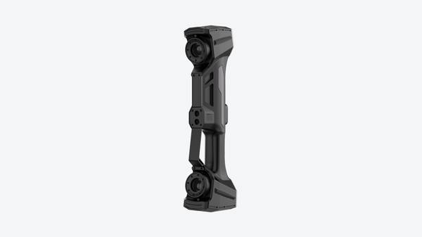
To avoid that mismatch, run every pilot using your own production parts, not vendor-provided samples. Pull parts with the actual surface finishes, edge breaks, and reflectivity that currently cause inspection bottlenecks. Have line-level quality staff operate the system after basic training, not the metrology specialist who attended the vendor workshop.
Three criteria matter most. First, repeatable results for your specific geometries and finishes. Scan the same part multiple times, in different orientations, with different operators. Compare deviation maps and GD&T callouts across runs. If runout tolerance or profile measurements drift between operators, the system is not ready for the floor.
Second, data integration. Export the scan mesh or point cloud into your current CAD/CAM and quality management stack without a manual conversion step. If an engineer has to rebuild the file in another package before analysis, you have added a hidden labor cost.
Third, throughput aligned to takt time. Time both single-part inspection and a realistic batch sampling routine. Include loading, scanning, data processing, and report generation. A scanner that measures quickly but stalls in post-processing can still miss your line cadence.
Use the table below as a field checklist during pilot trials.
| Core Criterion | On-Site Validation Step | Success Metric |
|---|---|---|
| Repeatable results for your part geometries and surface finishes | Scan the same production part three times with two line-level operators; compare deviation maps and key GD&T callouts | Maximum deviation between runs stays within your internal GR&R acceptance limit |
| Seamless data integration with current QMS and CAD/CAM software | Export scan data to your existing inspection or CAD software and complete one full analysis routine | No manual file conversion or rework; data opens directly in the target software |
| Throughput aligned with production takt time | Run single-part inspection and a batch sampling sequence under normal line conditions | Total cycle time, including processing and reporting, stays within takt time for both routines |
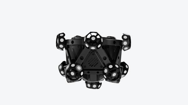
INSVISION industrial 3D scanners can be evaluated against these same criteria. For example, the industrial 3D scanner system offers a scanning area up to 1100 mm × 800 mm and tracker coverage up to 2600 mm × 2200 mm, which matters when you need to inspect large weldments or aerospace structures without repositioning the part multiple times.
The scanner accuracy is specified up to 0.020 mm and the tracker up to 0.025 mm, but the real validation step is whether that accuracy holds on your parts, in your environment, with your operators.
Do not accept a pilot report that only shows a single scan from a vendor engineer. Ask for raw, unedited runs from your own staff. If the vendor cannot support that test, the scanner measurement system is not ready for your production reality.
How INSVISION Scanner Measurement Aligns With Your Evaluation Goals
The moment a quality lead moves from datasheet review to on-floor validation, the evaluation criteria shift. You stop asking what a scanner can measure and start asking whether it can hold consistency in your environment, integrate with your inspection workflow, and keep pace with production without becoming another bottleneck.
INSVISION industrial 3D scanner measurement systems are built for that distinction. The engineering focus is not on controlled metrology lab performance alone. These units are designed to operate on active production floors, supporting near-line and in-line inspection for both high-volume runs and high-mix operations.
That matters when your GD&T callouts include tight profile tolerances on castings or stamped parts that arrive warm, oily, or still fixtured.
The most useful proof point is one your own team controls. Run a structured on-site pilot using your production parts and your quality standards. Test repeatability across shifts, data handoff into your existing software, and throughput against your current inspection method. That pilot is the lowest-risk way to verify whether INSVISION scanner measurement fits your evaluation goals before any purchasing decision gets made.
Final Validation Checklist + Common Scanner Measurement FAQs
A lot of teams assume a scanner either fits their inspection workflow or it doesn’t. The real risk isn’t capability — it’s failing to validate the scanner against your own parts, tolerances, and shift cadence before rollout.
Final Validation Checklist
- Confirm data export formats match your QMS and SPC software requirements.
- Time setup on three distinct part numbers, not one demo part.
- Verify operator training needs against your actual team skill level.
- Measure repeatability across ten consecutive scans of the same feature set.
- Assess throughput against takt time on your busiest production shift.
Common Scanner Measurement FAQs
Can scanner measurement meet ISO/ASME tight-tolerance requirements for aerospace or medical device components?
Yes, when the system is validated for the specific GD&T callouts involved. Ask for a gage R&R study on your part geometry before committing.
How does scanner measurement perform for high-mix low-volume production runs with frequent part changeovers?
Most precision 3D scanners handle changeovers well, but setup time varies by fixture strategy and part complexity. Test changeover time on at least three part numbers.
Do I need a temperature-controlled lab environment to get consistent scanner measurement results?
Not always. Many systems compensate for thermal drift, but large temperature swings on large parts can still affect repeatability. Validate in your actual environment.
What is the first step to test scanner measurement for my specific part portfolio?
Send a representative set of parts — including your tightest tolerance features — for an on-site pilot. Datasheet accuracy values mean little without your geometry.
Prioritize on-site pilot testing over datasheet claims. The decision should hinge on measured repeatability, setup time, and export compatibility in your own facility.
Hangzhou Insvision Technology Co., Ltd.
Address: Building 1, No. 1399 Liangmu Road, Yuhang District, Hangzhou, Zhejiang 311121, China
Copyright © Hangzhou Insvision Technology Co., Ltd. All rights reserved.
Copyright © Hangzhou Insvision Technology Co., Ltd. All rights reserved.