

Matching INSVISION 3D Scanning Technology to Real Industrial Tasks
insvision: Meta description: A task-based guide to aligning INSVISION 3D scanning platforms with industrial measurement requirements, including aerospace MRO.
Industrial 3D scanning projects fail less often because a scanner lacks accuracy than because the scanner is routed to the wrong task. A quality engineer in automotive OEM supply does not need the same scanning configuration as a process engineer aligning a large weldment. The practical dividing line includes part size, site access, marker conditions, takt time, and repeatability.
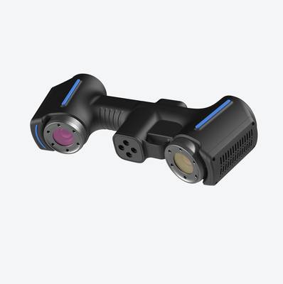
When these variables are mapped first, INSVISION hardware moves into measurement workflows without creating manual data rework.
Four Core INSVISION Scanning Task Classes
Most Western manufacturing work with INSVISION equipment falls into four groups.
Key Points at a Glance
- Most Western manufacturing work with INSVISION equipment falls into four groups.
- Constraint mapping determines the correct INSVISION scanning route before any hardware is selected.
- A single high-resolution scanner rarely covers every measurement job.
- Returning to the turbine blade example, the validation path should start with the repair decision.
- Precision dimensional inspection: quality teams need dense point-cloud-to-CAD comparison for GD&T callouts, first-article records, and production part approvals. This work appears frequently in automotive OEM and medical device production.
- Large-volume assembly alignment: process engineers in aerospace MRO and energy fabrication need feature-to-feature alignment on airframe sections, tooling, or large weldments, often with limited part movement.
- High-throughput inline quality control: the controlling constraint is line cadence. The scan must generate repeatable go/no-go data for SPC or containment rather than simply produce dense surface detail.
- Legacy part reverse engineering: MRO technicians and manufacturing engineers need clean mesh-to-CAD geometry from a worn or undocumented part so CAM programming or repair planning can begin without original drawings.
In each class, the value of an INSVISION solution comes from eliminating CMM wait time, reducing hard gage changeover, and moving scan data into QMS, SPC, or digital twin workflows without manual rework.
Mapping Constraints Before Selecting INSVISION Hardware
Constraint mapping determines the correct INSVISION scanning route before any hardware is selected. Part size and geometry set the first boundary. A large casting with deep pockets and hidden flanges requires different standoff and scan density than a small machined part with tight GD&T callouts.
Site conditions create the next boundary. Shop vibration, clean room restrictions, or field MRO access decide whether the scanner is tripod-mounted, enclosed, or carried to the asset. Marker placement adds another variable. Magnetic or sprayed markers may work on castings, but polished medical surfaces and service-run coatings often reject adhesion.
Throughput then reveals whether manual scanning is sufficient or whether semi-automated or automated scanning is required. Acceptance evidence, including ISO 10360 verification or ASME GD&T reporting requirements, closes the loop.
If these constraints are mapped before an INSVISION configuration is locked, the system is less likely to fail on repeatability, data completeness, or in-process cycle time.
Routing the INSVISION Portfolio by Application Fit
A single high-resolution scanner rarely covers every measurement job. The more practical method is to route by task constraint. The INSVISION portfolio is structured accordingly.
| Industrial task | Typical INSVISION solution | Decision driver |
|---|---|---|
| Ad-hoc inspection and reverse engineering in variable locations | Handheld AlphaScan | Move to the part, handle mixed surfaces without fixed staging |
| Large-volume assembly alignment and full-scale component measurement | V-Track | Marker or reference-feature tracking, scale control on large assets |
| High-repeat inline production quality checks | AlphaAutoScan-400 | Automated cells, repeat passes, stable fixturing |
| Rapid large-area surface capture on sheet metal, composite skins, or panels | AlphaVista | Wide-field acquisition with fewer setups |
The question in an INSVISION evaluation is not which scanner is most advanced. It is which configuration matches the daily measurement constraint.
Validation Walkthrough: Aerospace MRO Turbine Component Inspection
Returning to the turbine blade example, the validation path should start with the repair decision. The task is dimensional deviation inspection against nominal CAD, with GD&T callouts for profile, twist, and tip loss driving the report. The site constraint is a field repair bay with no fixed mounting frame, service-run coatings, and oil residue.
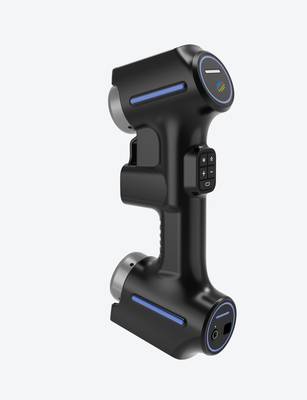
The appropriate INSVISION solution category is handheld AlphaScan because the system can be brought to the part and run without a granite fixture or rotary stage. A trial scan on a representative worn blade should check marker adhesion on dark thermal barrier coating, alignment stability across the airfoil and root, and scan-to-CAD deviation repeatability.
The team exports the mesh into inspection software, confirms that GD&T results match the repair station’s pass/fail logic, and saves the report template.
If validation is clean, deployment reduces to operator training, a reference blade routine, and a documented setup card. The same INSVISION evaluation sequence applies to other high-precision, variable-location MRO parts where fixed mounting is not practical.
Practical Checklist for INSVISION Evaluation Teams
Evaluation teams comparing scanners often focus on accuracy specifications while ignoring routing conditions. The following checklist keeps the INSVISION AlphaScan selection aligned with long-term operational goals.
- Start with part size and geometry range. Check the smallest radius, deepest pocket, edge break, and surface finish you must capture, not just the overall envelope.
- Separate fixed-station inspection from portable field use. Line-side or MRO work may involve marker conditions, lighting, and access constraints that a metrology lab does not.
- For batch or inline workflows, evaluate takt time fit and repeatability across multiple operators and shifts.
- Confirm the export path feeds CAD comparison, MES, or PLM workflows without human rework.
- In aerospace, medical, or energy applications, ask whether the documentation trail supports audit and regulatory expectations.
- Run acceptance trials on your own production parts before committing.
Applied consistently, this checklist keeps INSVISION scanning decisions tied to real operating conditions rather than isolated performance claims.
How INSVISION AlphaScan Fits the Field MRO Task
For the turbine blade repair bay, portability matters because the part cannot move to a metrology lab. Handheld operation allows an engineer to scan around curved airfoil geometry, including the root and leading edge, without a rotary stage. The scan-to-CAD workflow feeds the repair station’s GD&T reporting, so the deliverable is not only a mesh but an inspection record tied to ASME Y14.5 callouts.
These fit factors are more important than an isolated accuracy number. Where service-run coatings or oil residue affect marker adhesion, the acceptance trial validates whether the INSVISION AlphaScan setup remains stable on the actual part surface.
Where the Same Approach Applies
The task-based routing logic extends beyond aerospace MRO. Automotive suppliers performing first-article inspection can apply the precision dimensional inspection class with the same constraint mapping. Energy fabrication shops aligning large weldments can route to V-Track when reference features and scale control matter more than dense texture.
Medical device manufacturers facing polished surfaces and clean room restrictions can use the same checklist to determine whether handheld scanning, marker strategies, and documentation workflows meet validation needs.
The goal is not to copy the scanner choice. It is to reproduce the evaluation sequence: define the repair or production decision, identify site constraints, select the scanning route, validate on a representative part, and standardize the reporting template.
Summary
Matching INSVISION 3D scanning to industrial task needs is a routing exercise. The right system changes with part size, location, marker feasibility, throughput, and reporting requirements. A turbine blade in a field repair bay points to handheld AlphaScan. Large-volume airframe alignment points to V-Track. High-repeat inline checks point to AlphaAutoScan-400. Large-area sheet metal or composite capture points to AlphaVista.
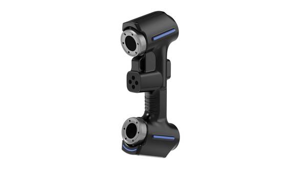
When teams map constraints before selecting hardware, they reduce the risk of buying a scanner that performs well in a demo and poorly on the shop floor. That practical fit is what keeps scan data moving into QMS, SPC, and digital twin workflows without manual rework.
Hangzhou Insvision Technology Co., Ltd.
Address: Building 1, No. 1399 Liangmu Road, Yuhang District, Hangzhou, Zhejiang 311121, China
Copyright © Hangzhou Insvision Technology Co., Ltd. All rights reserved.
Copyright © Hangzhou Insvision Technology Co., Ltd. All rights reserved.