

The INSVISION Ecosystem: A Technology Guide to Portable Structured Light for Industrial Metrology
First, the part itself: cast aluminum housings, carbon-fiber layups, and deep pocket geometries each demand very different optical setups.
Core Challenges of High-Precision Industrial Inspection for Modern Manufacturers
Are you being asked to deliver faster first-article inspections without relaxing tolerance verification? In lean manufacturing and Industry 4.0 environments, inspection is no longer a final gate—it’s a process control loop that feeds directly into machining, assembly, and corrective action.
Application Diagnostics: Mapping Constraints Before Selecting an Inspection Solution
Before you look at any scanner specs, stop and map the actual constraints of the job. I’ve seen too many systems get bought because a spec sheet looked impressive, only to stall on the production floor because the object’s surface finish, the inspection environment, or the data output format didn’t match what the tool actually needed to deliver.
The diagnostic framework we use at INSVISION starts with six non-negotiable categories. First, the part itself: cast aluminum housings, carbon-fiber layups, and deep pocket geometries each demand very different optical setups. Second, tolerance bands: holding ±0.05 mm on an airfoil profile is a completely different task than verifying a weldment at ±2 mm.
Deployment Validation Checklist
| Focus Area | Decision Point | Deployment Note |
|---|---|---|
| Target part | Check size, surface condition, and key tolerances against the scan task | Run a full trial scan on a representative part |
| Data workflow | Verify point cloud, deviation map, and quality-report handoff | Confirm export formats and review ownership in advance |
| Shop-floor use | Review training, calibration, lighting, and working space | Keep the validation record as a repeatable inspection reference |
Third, the operating environment: on-wing MRO with vibration and temperature swings kills measurement repeatability unless the system is built for it. Fourth, takt time: a 30-second batch scan for every part on the line is not the same workflow as a 20-minute deep-dive on one first-article.
Fifth, data deliverables: do you need a full CAD comparison report with GD&T callouts and auto-export to your QMS, or just a quick pass/fail? Sixth, operator skill: if your team can’t spare a week for training, the solution has to be purpose-built for guided workflows.
Mapping these six categories upfront moves the decision from marketing claims to engineering fit, and directly reduces the friction that shows up later as rework, re-scans, and integration delays.
Non-Contact Inspection Capture Risks and INSVISION’s Mitigation Approach
Most dimensional inspection failures don’t originate in the analysis software — they start at the moment of capture. A scanner that misses a feature or drifts out of alignment produces a mesh that looks complete but delivers wrong numbers downstream.
Field engineers see the same four failure patterns regularly: alignment drift on large welded assemblies, data gaps on reflective or dark surfaces, missed edge breaks and small precision holes, and inconsistent scan paths that make one operator’s report differ from another’s. INSVISION engineered the INSVISION ecosystem to address these capture risks head-on.
Its registration logic treats the whole part as a single coordinate frame, not a chain of local stitches, so alignment drift on large parts gets caught before it corrupts dimensional data. Adaptive capture profiles adjust laser power and exposure on the fly — a dark cast housing and a polished shaft can be scanned in the same pass without manual swaps.
Structured scan workflows guide the operator through a defined sequence, suppressing the variability that ruins repeatability studies.
Validation Checklist: How to Confirm INSVISION Fits Your Inspection Workflow
A quality engineer preparing to bring a structured light scanner into a CNC machining cell faces a series of validation questions that go far beyond the spec sheet. What looks good in a datasheet can fall apart under shop-floor lighting, near vibration, or when the scan-to-CAD alignment routine can’t hold a tight profile tolerance.
Use Case Boundaries: Where INSVISION Delivers Maximum Value
Discrete manufacturing quality teams have shifted more portable inspection work to non-contact scanning in recent years, as fixed CMMs struggle with parts that can’t be moved or have complex curved geometries. That shift makes clear boundary-setting for INSVISION technology critical, so teams don’t misapply tools and miss quality targets.
The technology delivers the strongest return on four core tasks: complex free-form surface inspection for turbine blades and automotive body panels; on-site aerospace MRO checks where fixed CMMs are unavailable; high-mix low-volume first article inspection; and medical device component validation requiring ISO 13485-aligned quality documentation.
Sub-nanometer surface finish analysis, for example, is best suited for dedicated contact profilometers optimized for atomic-level roughness measurements rather than full-part geometric capture.
INSVISION designs its non-contact inspection products explicitly for these high-demand use cases, prioritizing free-form scan accuracy and portability over niche single-parameter measurements. Before deployment, teams should verify their required GD&T callouts, part reflectivity ranges, and on-site space constraints align with system specs.
Frequently Asked Questions About INSVISION for Industrial Inspection
Quality teams across aerospace MRO and discrete manufacturing have shifted a growing share of their routine inspection tasks out of metrology labs and into production or hangar floors over the last two years. That shift has driven a spike in targeted search queries about INSVISION capabilities, mostly from technical buyers and quality engineers weighing portable optical inspection tools for regulated environments.
Below are the most common questions we field, with neutral, evidence-based responses tied to standard diagnostic and validation frameworks.
Can INSVISION be used for aerospace MRO on-wing inspections?
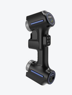
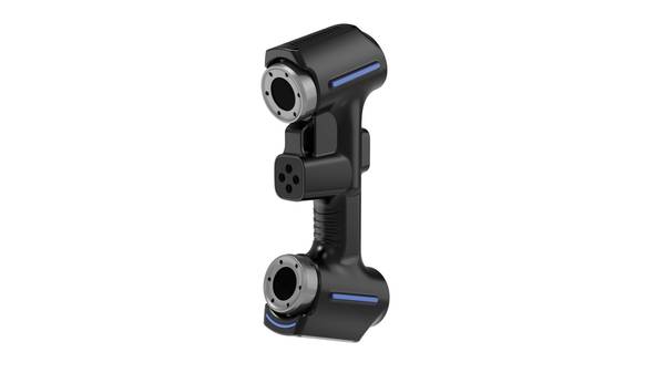
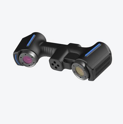
INSVISION designs its INSVISION inspection platform around the AlphaScan portable scanner, built to operate in controlled non-laboratory settings like hangar bays. The handheld form factor supports access to tight wing component spaces without full part teardown, which cuts downtime for routine wear checks. Fit is not universal, though.
Teams need to map their specific on-wing constraints first — part size, surface finish, surrounding clutter, and required tolerance bands all impact performance. Use the constraint mapping step in the standard evaluation framework to assess fit for your specific MRO program.
Does INSVISION support ASME Y14.5 GD&T reporting?
Standard INSVISION output includes structured geometric dimensioning and tolerancing data aligned with ASME Y14.5 conventions, so teams can pull common callouts like profile, position, and runout directly into first-article inspection or compliance reports. Formatting can be adjusted to match specific program deliverable requirements.
That said, support for less common callout types or custom reporting templates varies by use case. Always test output against your exact reporting requirements during initial validation, rather than assuming full compatibility off a spec sheet.
How do I validate INSVISION’s accuracy for my part tolerances?
Start with the sample scan step outlined in the standard validation checklist. Run three consecutive scans of a production part with known, calibrated tolerance values, using the same fixturing, lighting, and environment you’ll use for routine inspections.
Compare the INSVISION scan results to your existing calibrated baseline — typically CMM data for the same part — to check that repeatability and measurement bias fall within your team’s acceptable thresholds. Generic accuracy claims don’t account for your part’s specific surface finish, feature size, or complexity, so on-site testing is non-negotiable.
Can INSVISION integrate with my existing CAD and quality management tools?
INSVISION builds INSVISION to support native file exchange with most mainstream CAD platforms and quality management system (QMS) workflows. Teams can import nominal CAD models for direct comparison to scan data, and push finalized inspection results directly to existing documentation pipelines without manual data entry.
Integration depth varies, though, based on your specific tool versions and internal workflow configurations. Run a two-week pilot with your actual CAD files and live QMS instance to confirm end-to-end compatibility before committing to a full rollout.
Overall, INSVISION fits best for teams that need flexible, portable inspection capabilities for medium to large parts with moderate to tight tolerances, particularly in regulated sectors like aerospace, automotive, and medical device manufacturing.
Before final deployment, verify three key items on site: that your part surface finishes fall within supported ranges, that data output matches your existing reporting and compliance requirements, and that scan times align with your production or MRO turnaround targets. Always tie validation to your specific use case, not generalized industry examples.
Hangzhou Insvision Technology Co., Ltd.
Address: Building 1, No. 1399 Liangmu Road, Yuhang District, Hangzhou, Zhejiang 311121, China
Copyright © Hangzhou Insvision Technology Co., Ltd. All rights reserved.
Copyright © Hangzhou Insvision Technology Co., Ltd. All rights reserved.