

What Engineers Need to Know About 3D Scanners for CAD Workflows
INSVISION AlphaVista industrial 3D scanning application What a 3D Scanner for CAD Actually Delivers A 3D scanner for CAD is not simply a camera that creates a mesh.
The reality is that five operational constraints usually determine whether scan data will flow into a CAD assembly without hours of manual rework. This article explains the principles that govern 3D scanning for CAD integration, the core task classes that shape industrial demand, and the practical validation steps that separate a smooth digital thread from a broken one.
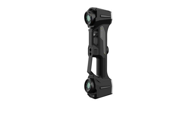
What a 3D Scanner for CAD Actually Delivers
A 3D scanner for CAD is not simply a camera that creates a mesh. It is a measurement system that captures dense surface point clouds and converts them into a coordinate system aligned with a nominal CAD model. The output is a deviation map, a watertight reverse-engineering mesh, or a digital twin geometry update—all forms that CAD platforms can ingest directly.
The scanner’s job is to eliminate the gap between the physical part and the digital design by providing dimensionally consistent data that preserves feature relationships, geometric tolerances, and surface continuity.
Scenario Snapshot
A practical way to read the article is through this scenario:
- What a 3D Scanner for CAD Actually Delivers: A 3D scanner for CAD is not simply a camera that creates a mesh.
- Four Core Task Classes That Define CAD Workflows: Industrial applications tend to fall into four distinct task categories, each with its own data-quality requiremen…
- Operational Constraints That Override the Datasheet: Accuracy alone is a poor selection criterion.
The underlying principle is triangulation-based or structured-light measurement, often combined with photogrammetry or marker tracking to maintain global accuracy across large volumes. When the scanner outputs a mesh, the file must retain a coordinate system that matches the CAD origin, or downstream alignment becomes a manual exercise in best-fit guesswork.
For CAD integration, the critical deliverable is not just point density; it is a metrology-grade dataset that can be imported into SolidWorks, CATIA, NX, or similar software without re-meshing, hole-filling, or coordinate realignment.
Four Core Task Classes That Define CAD Workflows
Industrial applications tend to fall into four distinct task categories, each with its own data-quality requirements.
| Task Class | Typical Application | Critical Data Deliverable |
|---|---|---|
| Reverse engineering | Redesigning legacy parts with no CAD data | Watertight, dimensionally consistent mesh that imports natively into CAD without manual repair |
| First article inspection | AS9102 / PPAP reporting | GD&T-aligned point cloud mapped directly to the CAD nominal model, generating audit-ready deviation colour maps |
| Digital twin geometry capture | Monitoring tool wear across production runs | Repeatable, low-variance scan data to update twin geometry as tooling evolves |
| Tooling verification | Line-side maintenance checks | Fast, on-site scan outputs compared against CAD tooling models to spot wear before unplanned downtime |
Each class imposes different demands on the scanner. Reverse engineering requires a mesh free of holes and topological errors. First article inspection demands that the point cloud registers to the CAD nominal with a known alignment uncertainty. Digital twin capture needs scan-to-scan repeatability, not just single-scan accuracy.
Tooling verification prioritises speed and portability, often in spaces where tripods are impractical.
Operational Constraints That Override the Datasheet
Accuracy alone is a poor selection criterion. Five operational factors typically dominate the decision process:
- Part size envelope: A large casting or turbine blade requires wide-area capture without stitching drift. If the scanner cannot maintain global accuracy across the full surface, the resulting point cloud will not align cleanly with reference CAD surfaces.
- Site mobility: Work on an aircraft fuselage, a wind turbine blade mould, or a press-shop die often demands a handheld scanner that moves around the part, not a fixed-setup system that requires moving the part to the scanner.
- Marker feasibility: Some surfaces cannot be marked with adhesive targets. Scanner tracking must then rely on geometry features or hybrid tracking methods that do not degrade accuracy.
- Takt time per part: In production environments, the time from unpacking to CAD-ready data must fit within the line’s cycle time. A scanner that delivers excellent accuracy but requires lengthy post-processing can become a bottleneck.
- Batch repeatability: For high-volume repeat measurements, scan-to-scan variance matters more than absolute accuracy. Low variance ensures that digital twin updates and trend monitoring remain trustworthy.
How INSVISION Routes Solutions by Task Profile
INSVISION does not promote a single “best” scanner. Instead, the portfolio is routed by mapping each solution’s strengths to the physical constraints and data deliverables a buyer actually faces. The routing framework starts with the part, the inspection task, and the site conditions, then narrows to the scanner that can deliver the required mesh quality and alignment integrity for the target CAD environment.
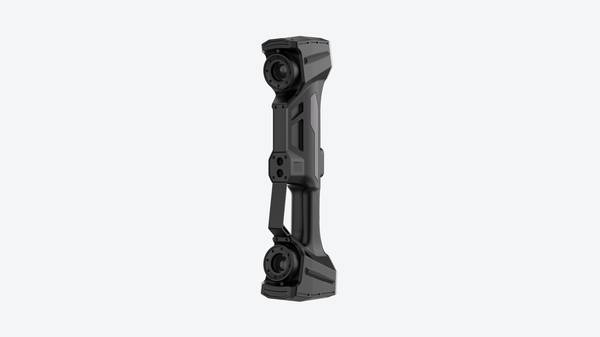
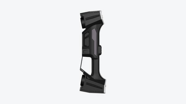
For extra-large parts that cannot be moved—aircraft sections, full automotive body sides, wind blade tooling—the AlphaVista large-format handheld 3D scanner for CAD is designed to remove the fixed-position bottleneck. Its wide scan envelope allows a technician to walk around the structure and capture dimensional data directly into the CAD coordinate system.
The data is pre-formatted so that meshes drop into standard GD&T software for profile and flushness analysis, or into reverse engineering packages where Class A surfaces must be reconstructed from scan data.
The value of the AlphaVista in a CAD workflow is not just capture speed. It is the reduction in post-scan rework: the mesh alignment, hole filling, and coordinate transformation steps that eat into lean cycle time targets. Because the scanner outputs data in a CAD-ready format, the digital thread from physical part to deviation map or CAD model remains intact, without the manual data massaging that often introduces errors.
Practical Validation Steps for CAD Workflow Compatibility
Before committing to a scanner, teams should validate integration with their actual CAD platform and shop-floor conditions. The following steps often reveal incompatibilities that a spec sheet hides.
- Import path verification: Import the scanner’s mesh and aligned CAD model into the team’s existing platform (SolidWorks, CATIA, NX). Confirm that the coordinate system, feature tree relationships, and units are preserved.
- GD&T tolerance check: Select a representative part with known GD&T callouts—flatness, profile, true position, runout. Scan it and verify that the delivered point density resolves those tolerances as defined on the drawing.
- Deployment timing: Measure the elapsed time from unpacking to first scan under actual shop-floor conditions, not a demo room. Include calibration, if required, and any environmental stabilisation.
- End-to-end processing cycle: Run a part of typical size—such as a casting or weldment—through the full workflow: scan, mesh generation, CAD alignment, and report creation. Assess whether the total time meets takt time requirements.
Quick Decision Checklist for CAD Scanner Selection
- Confirm part size category: small, medium, large, extra-large.
- Identify primary scan location: controlled lab, shop floor, field/in-situ.
- Determine whether adhesive markers can be applied to scan surfaces.
- Define required throughput per part for CAD alignment.
- Assess batch volume: one-off, low-mix, or high-volume repeat.
- For cross-workflow needs—e.g., large-part field scanning combined with high-volume lab first-article checks—request custom INSVISION routing to align multiple solutions with the CAD ecosystem.
On-site verification should also include ambient vibration levels, part access around fixturing, and fixed-setup power access. Matching scanner capabilities to these specific task constraints drives long-term CAD workflow efficiency and consistent quality outcomes.
Common Misconceptions About 3D Scanners for CAD
Q: Higher accuracy always means a better CAD model.
A: Accuracy is only one variable. A scanner with 0.020 mm volumetric accuracy but poor repeatability or slow scan-to-model throughput can produce a CAD mesh that requires more manual rework than a slightly less accurate scanner with better repeatability and faster alignment. The metric that matters is how little post-processing is needed to get a usable CAD model.
Hangzhou Insvision Technology Co., Ltd.
Address: Building 1, No. 1399 Liangmu Road, Yuhang District, Hangzhou, Zhejiang 311121, China
Copyright © Hangzhou Insvision Technology Co., Ltd. All rights reserved.
Copyright © Hangzhou Insvision Technology Co., Ltd. All rights reserved.