

Closing the First-Article Inspection Gap on Large Aerospace Panels with a 3D Measurement System
When a composite fuselage panel exits the autoclave, the quality clock starts ticking. Production needs the assembly jig freed for the next build.
Pre-Scan Alignment: Locking Inspection Criteria Before the First Laser Pulse
Aerospace and automotive OEMs pressing for closed-loop digital quality workflows have moved the handoff upstream. Rather than scanning a part and then debating what should have been measured, leading teams now define inspection criteria before any laser strikes the surface. During pre-scan alignment, quality and process engineers jointly mark up the CAD model.
They identify critical GD&T callouts, surface tolerance zones, and FAA-required compliance checkpoints. Standoff distance, resolution, and coverage paths are agreed upon in the scan plan. The result is a shared acceptance protocol that eliminates the re-scan loops and late-stage disagreements that plague first-article inspections.
Scenario Snapshot
A practical way to read the article is through this scenario:
- Pre-Scan Alignment: Locking Inspection Criteria Bef…: Aerospace and automotive OEMs pressing for closed-loop digital quality workflows have moved the handoff upstream.
- On-Station Scan Execution with the INSVISION AlphaV…: At the assembly jig, the INSVISION AlphaVista 3D measurement system lets quality technicians capture complete fuse…
- Point Cloud Processing and Cross-Team Deviation Ana…: Raw point cloud data from the INSVISION 3D measurement system imports directly into inspection software.
On-Station Scan Execution with the INSVISION AlphaVista 3D Measurement System
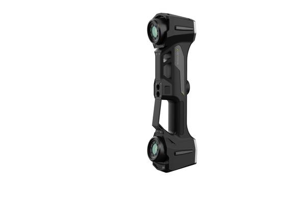
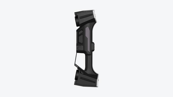
At the assembly jig, the INSVISION AlphaVista 3D measurement system lets quality technicians capture complete fuselage panel geometry without moving the part. A handheld scanner walks the curved surface, while a rugged tablet beside the station displays a live point-cloud map with color-coded coverage density.
Deployment Validation Checklist
| Focus Area | Decision Point | Deployment Note |
|---|---|---|
| Target part | Check size, surface condition, and key tolerances against the scan task | Run a full trial scan on a representative part |
| Data workflow | Verify point cloud, deviation map, and quality-report handoff | Confirm export formats and review ownership in advance |
| Shop-floor use | Review training, calibration, lighting, and working space | Keep the validation record as a repeatable inspection reference |
The moment a fastener row, edge margin, or curvature profile falls below the required point density, the engineer sees it and asks the technician for a quick extra pass. There is no need to offload data, run a separate coverage check, and recall the part hours later. Because the scanner is handheld and lightweight, the operator works around fixed tooling without repositioning tripods or trackers.
After the scan, the dataset saves directly to the shared digital repository. Quality pulls it for GD&T evaluation; process engineering feeds it into trend analysis. The closed-loop handoff between data capture and actionable information shrinks from hours to minutes.
Point Cloud Processing and Cross-Team Deviation Analysis
Raw point cloud data from the INSVISION 3D measurement system imports directly into inspection software. There it aligns to the nominal CAD model and processes into full-surface deviation maps in minutes, not hours. Quality and process teams access the same shared digital dataset, so they review flagged out-of-tolerance features together without paper-handoff lags.
Instead of guessing from discrete CMM points, teams assess root causes like tooling drift or assembly sequence misalignment directly from the full 3D scan data. This workflow works best for high-mix, complex-component lines where discrete sampling misses critical deviation patterns.
On site, teams should verify that CAD alignment matches GD&T datums before sign-off and confirm that flagged features tie to physical part marks for traceability. Standard handoff checkpoints include confirmed CAD alignment validation, out-of-tolerance feature flagging with geometric context, root cause hypothesis tagging, and corrective action sign-off tied to the scan record.
Standardized Reporting and Closed-Loop Reinspection
The final output of a 3D measurement system workflow goes far beyond a pass/fail result. With INSVISION, each inspection closes with a standardized AS9100-compliant report: a color-coded deviation heatmap overlaid on the CAD model, a summary table of every GD&T callout checked against tolerance, and the full point cloud archive for complete traceability.
That archive is more than a record—it is the foundation for closed-loop reinspection. When the assembly team adjusts a fixture, shim placement, or fastening sequence, they don’t start from scratch. The same pre-defined scan plan is triggered again, capturing only the zones affected by the change. Minutes later, a new deviation map confirms whether the adjustment moved the feature into spec or introduced a different drift.
This tight loop between production and quality feedback shrinks first-article approval timelines and directly feeds continuous improvement metrics.
The approach scales well beyond fuselage panels. For wind turbine blade root sections, heavy equipment chassis weldments, or any large-part assembly where slight misalignment cascades into downstream fit issues, the combination of traceable reporting and targeted reinspection scans keeps process corrections fast and verifiable.
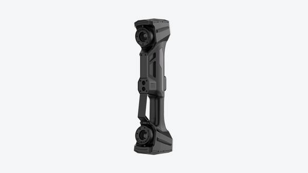
The key is moving the measurement system to the part, locking down inspection criteria before scanning, and building a shared data pipeline that replaces the paper report with a single source of truth. For engineering teams managing high-stakes, large-format inspections, that shift in workflow turns the 3D measurement system into a production tool, not a lab instrument.
Hangzhou Insvision Technology Co., Ltd.
Address: Building 1, No. 1399 Liangmu Road, Yuhang District, Hangzhou, Zhejiang 311121, China
Copyright © Hangzhou Insvision Technology Co., Ltd. All rights reserved.
Copyright © Hangzhou Insvision Technology Co., Ltd. All rights reserved.