

Scanner CAD CAM: How Large-Format 3D Scanning Turns Physical Parts into Production-Ready CAD Models
Scanner CAD CAM: How Large-Format 3D Scanning Turns Physical Parts into Production-Ready CAD Models. The term “scanner CAD CAM” doesn’t point to a single box of hardware.
What “Scanner CAD CAM” Actually Means in an Industrial Context
Scanner CAD CAM is a data pipeline, not a feature checkbox. The scanner captures dense point clouds from a physical surface. That raw data goes through alignment, noise reduction, and meshing to become a watertight polygon model.
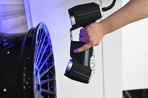
For CAD and CAM use, the mesh must be converted into a format that parametric modelers can read — typically through a process of domain segmentation, surface fitting, and finally CAD feature extraction. The deliverable is no longer a mesh but a solid or surface model in STEP, IGES, or native CAD formats.
Deployment Validation Checklist
| Focus Area | Decision Point | Deployment Note |
|---|---|---|
| Target part | Check size, surface condition, and key tolerances against the scan task | Run a full trial scan on a representative part |
| Data workflow | Verify point cloud, deviation map, and quality-report handoff | Confirm export formats and review ownership in advance |
| Shop-floor use | Review training, calibration, lighting, and working space | Keep the validation record as a repeatable inspection reference |
On the inspection side, the same pipeline flips direction: the scanned mesh is aligned to a reference CAD model, and deviation analysis produces a color map that highlights where the physical part drifts from nominal. Both paths demand that the scanner generate data with enough resolution and accuracy to make downstream decisions meaningful.
That is why industrial workflows care less about scan speed in isolation and more about the stability of the coordinate data across a large measurement volume.
Scenario Snapshot
A practical way to read the article is through this scenario:
- What “Scanner CAD CAM” Actually Means in an Industr…: Scanner CAD CAM is a data pipeline, not a feature checkbox.
- What makes the workflow practical is that modern: What makes the workflow practical is that modern software can handle much of the heavy lifting.
- Handheld scanners built for large format work are: Handheld scanners built for large-format work are designed around a different set of constraints than desktop or r…
What makes the workflow practical is that modern
What makes the workflow practical is that modern software can handle much of the heavy lifting. AI-driven alignment routines now match scanned data to CAD reference models automatically, reducing operator error. Real-time mesh generation lets users see coverage and inspect gaps while scanning, which is particularly valuable on large freeform surfaces where missing a section means a return trip to the shop floor.
The CAD-to-CAM handoff then becomes straightforward: once the scanned geometry is finalized as a CAD solid, CAM software can generate toolpaths for milling, EDM electrodes, or 3D printing supports. The scanner is not the hero of that story. It is the disciplined data source that keeps the rest of the chain from drifting.
Handheld scanners built for large format work are
Handheld scanners built for large-format work are designed around a different set of constraints than desktop or robot-mounted systems. They must maintain volumetric accuracy across distances that can exceed several meters, often on parts with deep draws, subtle curvature, and limited access.
The AlphaVista large-format handheld 3D scanner from INSVISION tackles this by combining a wide field of view with high-density point acquisition, so an operator can capture a car door inner panel or a wind turbine blade mold section without stitching dozens of small patches.
The scanner delivers 0.020 mm industrial metrology-grade accuracy, which is tight enough for precision assembly hole inspection on large tooling fixtures.
The connection to CAD works in two directions
The connection to CAD works in two directions. First, the scanner can import a reference CAD model before the scan begins. The system then uses that model to guide the acquisition, a method sometimes called CAD-driven task creation. As the operator scans, the software aligns the live data to the CAD model automatically, generating a real-time color deviation map.
Hangzhou Insvision Technology Co., Ltd.
Address: Building 1, No. 1399 Liangmu Road, Yuhang District, Hangzhou, Zhejiang 311121, China
Copyright © Hangzhou Insvision Technology Co., Ltd. All rights reserved.
Copyright © Hangzhou Insvision Technology Co., Ltd. All rights reserved.