

Measuring Reflective Industrial Parts: Scanning Challenges and Workflow Design for Mirror-Finish Surfaces
A polished turbine blade, a chrome-plated mold cavity, a freshly machined aluminum wheel hub — these components share a surface quality that makes conventional
Reflective surfaces create a cascade of metrology problems. Blue laser technology, as implemented in the INSVISION AlphaScan handheld scanner, can reduce the need for developer sprays in many cases, but intelligent scanning still depends on technique. The scanning angle, ambient light control, and exposure settings must be tuned to the specific reflection behavior of the material.
A nickel-plated injection mold reflects light differently than a glass-bead-blasted casting with residual oil film. Understanding the object before picking up the scanner is what separates consistent data from a failed scan session.
Deployment Validation Checklist
| Focus Area | Decision Point | Deployment Note |
|---|---|---|
| Target part | Check size, surface condition, and key tolerances against the scan task | Run a full trial scan on a representative part |
| Data workflow | Verify point cloud, deviation map, and quality-report handoff | Confirm export formats and review ownership in advance |
| Shop-floor use | Review training, calibration, lighting, and working space | Keep the validation record as a repeatable inspection reference |
Part Profile: Geometry, Surface Condition, and Inspection Targets
Typical reflective industrial parts fall into three broad categories. The first includes polished metal components — turbine blades, bearing journals, hydraulic rods — where surface roughness Ra can be below 0.1 µm. The second covers as-machined parts with directional tool marks that create anisotropic reflection.
The third involves dark or coated surfaces, such as black anodized aluminum brackets, which absorb much of the light and return a weak signal.
Practical Workflow
- Part Profile: Geometry, Surface Condition, and Inspection… — Typical reflective industrial parts fall into three broad categories.
- Detection Pain Points: Why Shiny Surfaces Break Standard… — The core problem is overexposure and specular reflection.
- Scan Strategy: From Surface Preparation to Data Capture — The INSVISION AlphaScan handheld scanner uses blue laser projection with a dynamic exposure adjustment that reacts to local refle…
- Inspection Data Loop: From Point Cloud to Actionable Repo… — Once the raw data is captured, the SMARPARA Q software aligns the scan to the reference CAD model using best-fit or feature-based…
Geometric complexity compounds the difficulty. Deep pocket features, thin walls under 2 mm, and steep draft angles introduce occlusions. A mold cavity for a headlamp housing, for example, combines a high-gloss P20 steel surface with dozens of ribs and bosses. The inspection target is often a full 3D comparison against CAD, with profile tolerance zones of ±0.05 mm or tighter on critical sealing surfaces.
Traditional touch-probe CMMs can capture individual points on such surfaces without reflection issues, but they are too slow to map the entire freeform geometry. A 3D scanner must gather millions of points across the entire surface to produce a meaningful deviation color map, and it must do so without losing data on the shiniest regions.
Detection Pain Points: Why Shiny Surfaces Break Standard Scanning Workflows
The core problem is overexposure and specular reflection. When a laser line hits a mirror-like surface, most of the energy reflects away from the scanner’s cameras instead of scattering back. The result is a missing stripe in the scan data — a hole in the mesh that later requires tedious filling or re-scanning.
Even when the laser is partially visible, the intensity can saturate the sensor, creating a bloom effect that blurs the edge of the line and reduces measurement accuracy.
Secondary issues include inconsistent point density across the part. A single scan pass may yield dense, clean data on matte sidewalls but sparse, noisy data on the polished top surface. When the alignment algorithm tries to register multiple scans, this uneven distribution can cause drift, especially on cylindrical or symmetric parts where geometric features are scarce.
For parts with thin walls, the heat from handling or clamping can introduce deformation that the scanner must distinguish from genuine dimensional deviation. Without a controlled workflow, operators end up spending more time fixing data than analyzing it.
Scan Strategy: From Surface Preparation to Data Capture
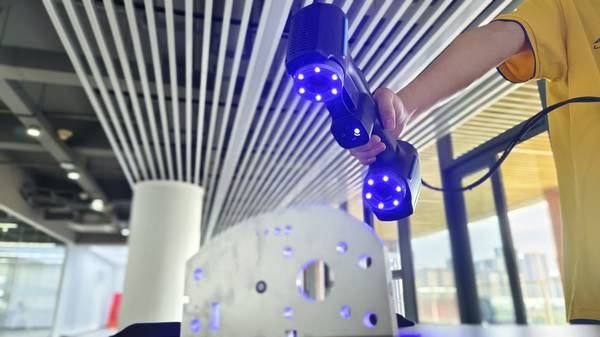
The INSVISION AlphaScan handheld scanner uses blue laser projection with a dynamic exposure adjustment that reacts to local reflectivity. The shorter wavelength of blue light reduces subsurface scattering on metallic surfaces, and the AI-driven algorithms in the 3D INSVISION software help reconstruct surfaces even when the raw signal is patchy. That said, a practical scan strategy still matters.
Start by cleaning the part. Fingerprints, coolant residue, and fine dust degrade reflection consistency and create false surface texture. For parts that can tolerate it, a light application of a certified metrology spray — one that deposits a thin, removable layer under 2 µm — can eliminate reflection issues entirely.
On parts where spraying is not allowed, such as fuel-wetted aerospace components, the scanner’s multiple exposure modes can be tuned. A common approach is to scan at a slight off-axis angle, avoiding the direct specular reflection back into the cameras. The operator can also use masking or bracketing: capturing the same area at different exposure settings and letting the software merge the usable data.
For parts with deep cavities or narrow slots, the AlphaScan’s handheld form factor allows the operator to orient the scanner into the feature, using the live preview to verify coverage. Alignment markers or target stickers placed on adjacent non-critical surfaces help maintain registration accuracy across multiple scans.
The goal is to generate a complete mesh with uniform point spacing, ideally within 0.05 mm of the CAD nominal, before any data processing begins.
Inspection Data Loop: From Point Cloud to Actionable Report
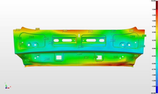
Once the raw data is captured, the SMARPARA Q software aligns the scan to the reference CAD model using best-fit or feature-based alignment. The deviation analysis then maps every point against the nominal geometry. For a reflective part, the first check is to verify that the shiny areas did not produce false positives.
A tight tolerance band on a polished surface can show apparent deviations that are actually noise from residual reflection. The analysis software can filter out points with low confidence values, but the operator must review the histogram and color map for plausibility.
GD&T callouts such as flatness, profile of a surface, or position of a bore are extracted directly from the scan data. The software supports standard geometric dimensioning and tolerancing tools, and the report can be exported in formats that integrate with the manufacturer’s quality documentation system.
If a part fails inspection, the same scan data can be used to guide rework — comparing the as-built surface to the CAD model and identifying the exact areas that need material removal or adjustment.
The INSVISION ecosystem closes the loop by allowing the same scan file to be used for reverse engineering, 3D printing of fixtures, and laser projection of part outlines during assembly, reducing the number of separate measurement setups.
Assessing a scanning solution for reflective industrial parts comes down to a few practical checks. Evaluate the scanner’s performance on a sample part from your own production line, not a vendor’s optimized demo piece. Look at the point cloud quality on the most challenging surface, and measure the time from scan start to a complete inspection report.
A system that forces operators to re-scan the same shiny region multiple times will slow the entire quality workflow. The right tool, combined with a disciplined scan strategy, turns reflective surfaces from a measurement obstacle into just another surface type in the inspection routine.
Hangzhou Insvision Technology Co., Ltd.
Address: Building 1, No. 1399 Liangmu Road, Yuhang District, Hangzhou, Zhejiang 311121, China