

Weld Seams Are Not Uniform Surfaces: Adapting 3D Inspection to Real Joint Geometry
A weld seam is rarely a smooth, predictable bead. In heavy fabrication, pressure vessels, and automotive structures, the seam winds across plates that may not s
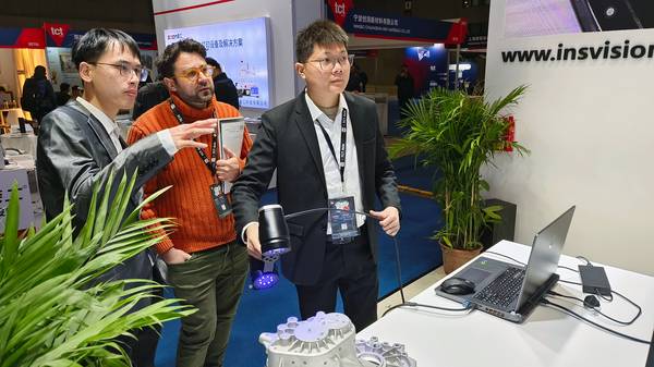
This is where a handheld 3D scanner like the INSVISION AlphaScan changes the options. The scanner does not force the operator to cut a coupon, apply a contrasting developer, or move the part to a controlled environment. The blue laser and onboard AI-based depth reconstruction work on dark, reflective, and uneven surfaces without requiring spray coating. But the technology alone does not solve the problem;
the way the scan is planned around the specific seam geometry makes the difference between a clean deviation map and a noisy dataset that no one trusts. The rest of this article walks through the object characteristics of real weld seams, the inspection difficulties they create, and the scanning-to-report workflow that turns point clouds into actionable quality data.
What a Weld Seam Actually Looks Like to a Measurement System
A weld bead is not a single geometric feature. It is a zone that includes the cap, the toes where the weld meets the parent material, the heat-affected zone edges, and in many cases small undercuts, overlaps, or porosity pockets. The surface can range from a smooth TIG finish to a rough, spatter-covered stick weld. On fillet welds, the angle between the two plates creates a narrow valley that is difficult to illuminate evenly.
On butt welds in thick plate, the seam may be ground flush, leaving only subtle surface variations to indicate the joint. In thin-walled tubing, the seam might be slightly recessed, requiring the scanner to capture the depression depth without losing the adjacent wall as a reference.
Selection Dimensions and Field Checks
| Focus Area | Decision Point | Deployment Note |
|---|---|---|
| What a Weld Seam Actually Looks Like to a Measurement S… | A weld bead is not a single geometric feature. | It is a zone that includes the cap, the toes where the weld meets the parent material, the heat-affected zone edges, and in many cases small und… |
| Where Geometry and Access Create Inspection Blind Spots | The real difficulty with weld seam inspection is not the cap — it is the areas that are partially hidden. | A pipe-to-pipe T-joint leaves a crescent-shaped root that is only visible from certain angles. |
| Building a Reliable Dataset from Weld Scans | Once the raw point cloud is captured, the data pipeline must handle several challenges specific to weld seams. | The first is alignment. |
| When the Weld Is the Only Benchmark | Not every weld seam has a CAD model to compare against. | In repair welding, reverse engineering, or when inspecting cold rolling mill rolls where the original model is lost, the benchmark must be a phy… |
The optical response of the weld zone is also inconsistent. The cap might be matte, the adjacent base metal reflective, and the root of a gap nearly black. For a scanner that relies on structured light, this mix of albedo and roughness can cause dropout or floating data unless the exposure and laser power are adjusted dynamically.
INSVISION’s AlphaScan addresses this with a combination of multi-line blue laser patterns and an AI-driven exposure control that adapts within a single scan pass. The result is that the scanner holds onto the seam profile even as the surface appearance shifts, which is critical when the inspection goal is to compare the as-built weld to a CAD nominal or to a pre-qualified reference weld.
Where Geometry and Access Create Inspection Blind Spots
The real difficulty with weld seam inspection is not the cap — it is the areas that are partially hidden. A pipe-to-pipe T-joint leaves a crescent-shaped root that is only visible from certain angles. A long seam on a box section may pass behind a mounting bracket, making it impossible to scan in one continuous sweep. Lap joints create a step that casts a shadow on the lower plate if the scanner is held at the wrong angle.
Deep grooves before backfill, typical in multi-pass welds, behave like narrow cavities where the laser must strike at a near-perpendicular angle to return usable data.
In these situations, the scan strategy must be built around the object’s access constraints. Instead of trying to capture the entire seam in one pass, the operator sections the seam into short, overlapping segments, tilting the scanner to reach into the groove or behind the obstacle.
The AlphaScan’s handheld form factor and lightweight body make it possible to hold the scanner at odd angles for several minutes without fatigue, and the real-time preview on the connected tablet shows exactly where coverage is missing. The operator can then revisit those areas immediately, rather than discovering the gap only after returning to the desktop.
This kind of in-field feedback loop is especially important on large weldments where re-mobilizing the scanner later is time-consuming and costly.
Building a Reliable Dataset from Weld Scans
Once the raw point cloud is captured, the data pipeline must handle several challenges specific to weld seams. The first is alignment. Without a full CAD model, the software needs to use the surrounding parent material as a stable reference, because the weld itself is variable.
INSVISION’s 3D INSPECTION software (or SMARPARA Q for more advanced GD&T workflows) aligns the scan to a CAD model or to a reference scan using the rigid body surfaces away from the seam. This ensures that the actual weld deviation is not absorbed into a misalignment error.
The second challenge is filtering. Weld spatter, dust, and edge artifacts can create noise that looks like surface deviation. The software’s intelligent filtering separates these outliers without smoothing the real weld contour.
The operator then isolates the weld zone using a virtual gauge or a section plane, and the software generates a color map that shows overfill, underfill, undercut, and toe misalignment relative to the tolerance envelope. The color map is not just a picture — it is a direct visual record of where the seam fails to meet the specification, and it can be linked to a specific location on the part with annotation labels.
The final step is the report. For a typical batch inspection, the report includes the deviation map, a few critical cross-section measurements, and a pass/fail summary against the weld class.
The entire process from scan to report can be completed in the time it takes to inspect the same seam with a bridge gauge and a fillet weld gauge, but with the advantage that the 3D scan stores the full geometry, not just a few spot measurements. That means if a quality engineer later questions an undercut measurement, the original scan data is available to re-slice the seam at any location.
When the Weld Is the Only Benchmark
Not every weld seam has a CAD model to compare against. In repair welding, reverse engineering, or when inspecting cold rolling mill rolls where the original model is lost, the benchmark must be a physical reference part. One documented INSVISION workflow uses a “good” roll as the master, scanning it with AlphaScan and then comparing subsequent welds or repairs to that master scan.
The same approach applies to weld seams on pressure vessel nozzles, where a qualified first article weld is scanned and stored as the golden reference. All following welds are then aligned and compared to that reference, with deviation maps showing exactly where the new weld deviates from the approved profile.
This approach closes the inspection loop. The scanner does not need a perfect CAD model; it only needs a reference that represents the acceptable condition. The weld seam becomes its own standard, and the 3D data makes the comparison objective and repeatable.
For production environments where weld quality directly affects fatigue life or pressure integrity, having a digital record of every seam against a known good reference changes the conversation from “it looks acceptable” to “it matches within 0.15 mm of the approved profile.” The AlphaScan handheld scanner, combined with the software’s ability to handle reference-based comparisons, makes this workflow practical on the shop floor, not just in a metrology lab.
The result is a weld inspection process that starts with the object’s real shape and ends with a traceable digital record that can be archived, re-analyzed, and shared without ever touching the part again.
Hangzhou Insvision Technology Co., Ltd.
Address: Building 1, No. 1399 Liangmu Road, Yuhang District, Hangzhou, Zhejiang 311121, China