

When Curved Profiles Defy Traditional Gauges: 3D Inspection of Spatial Dimensions
A machined bracket with sweeping organic curves lands on the inspection bench. The engineer reaches for a caliper, then a height gauge, then a radius template —
Typical Object Profiles That Demand 3D Dimensional Inspection
The parts that break conventional metrology tend to share a few traits. They are rarely prismatic. Instead, they carry swept wing profiles, deep pocket floors, or Class A surfaces where the eye will catch any deviation from the design intent. In automotive body shops, it might be a door inner panel with flanges, beads, and trim holes that all need to sit within a 0.3 mm flushness envelope.
In aerospace, a composite fairing with a double curvature and a 520 nm laser‑friendly surface finish can be measured in minutes, but the same part riddled with shiny gel coat will challenge older scanning hardware. Injection molds introduce another layer: the core and cavity need separate scans, and the curved parting line must be inspected both as a free state single part and as a mated assembly.
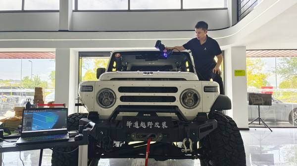
The AlphaScan handheld scanner handles these variations with a 520 nm blue laser that is less sensitive to moderately reflective surfaces, which means fewer coats of matte spray and better preservation of the part’s as‑built condition.
Capability and Deployment Mapping
| Focus Area | Decision Point | Deployment Note |
|---|---|---|
| Typical Object Profiles That Demand 3D Dimensional Insp… | The parts that break conventional metrology tend to share a few traits. | They are rarely prismatic. |
| Core Challenges of Spatial Dimensions and Curved Surfac… | Measuring a curved profile is not simply a matter of higher point density. | The real struggle is establishing a datum that means something on a part that lacks flat faces. |
| Scan Strategy and Data‑Processing Workflow | A structured scan path is what separates a repeatable inspection from a one‑off measurement. | For a part with deep cavities and undercuts, the approach usually starts with a coarse registration sweep that captures the overall volume and t… |
| From Inspection Report to Process Reuse | The real value of a 3D inspection of spatial dimensions and curved profiles emerges when the data feeds back into the manufacturing process. | A die casting supplier might scan the first three shots of a new mold, compare them in 3D INSVISION, and see that the warp trend is consistent b… |
What makes these objects hard to inspect is not just the curvature but the fact that the critical dimensions rarely sit on a single plane. A cooling duct may have an inlet flange that must match a bolt pattern while the outlet blends into an oval section whose cross‑sectional area is the real control dimension. Traditional tools capture the flange but ignore the blended middle.
When the object is large — a yacht hull plug, a wind turbine blade root — the sheer scale forces the inspector to stitch together multiple reference frames, and the uncertainty of the stitch can eat up the tolerance budget before any measurement is recorded.
INSVISION’s V‑Track optical tracking system attacks this directly by keeping the coordinate system anchored to the part, allowing the scanner to move freely without losing the global reference.
Core Challenges of Spatial Dimensions and Curved Surfaces
Measuring a curved profile is not simply a matter of higher point density. The real struggle is establishing a datum that means something on a part that lacks flat faces. If the part is a carbon fiber seat shell, its only machined feature might be four mounting bushings. The rest of the geometry is a flowing composite surface that was never intended to be gaged with a sine bar.
In such cases, the alignment strategy — often a best‑fit to the CAD model with a weighted constraint on the bushings — determines whether the subsequent color map is a true representation of deviation or a misleading artifact of the registration. Thin‑walled parts add another layer of complication: a plastic fascia may deform under its own weight depending on how it is supported.
The scan must capture the part in a restrained state that mimics the assembly condition, and the software must be able to compare that scan to the nominal CAD model without forcing an unrealistic rigid‑body alignment.
Surface finish and optical behavior are equally important. A polished extrusion die cavity can generate specular reflections that blind a scanner, while a heavily oxidized steel casting might absorb too much light to return a clean profile. The AlphaScan’s blue laser and adjustable exposure settings help, but the operator still needs to understand the interaction between laser wavelength and material.
Dark, transparent, or highly textured surfaces often require a brief test patch to confirm that the exposure and gain are dialed in before the full scan begins. INSVISION’s 3D INSVISION software provides a live preview of the point cloud quality, so the operator can spot a noisy patch on a deep pocket floor and re‑scan that area immediately rather than discovering the gap during post‑processing.
Scan Strategy and Data‑Processing Workflow
A structured scan path is what separates a repeatable inspection from a one‑off measurement. For a part with deep cavities and undercuts, the approach usually starts with a coarse registration sweep that captures the overall volume and the main locating features. The operator then works through a series of targeted passes: one for the deep pocket, one for the perimeter flange, one for the hole pattern.
Because the AlphaScan is handheld, the path can adapt to the part rather than forcing the part to rotate on a turntable. The INSVISION V‑Track system keeps the scans aligned even when the part is too large to move, which is common with large‑format aerospace tooling and marine components.
Once the raw point cloud is captured, the processing moves into 3D INSVISION. The software aligns the scan to the reference CAD model using a combination of manual feature picks and automatic best‑fit algorithms.
The GD&T toolkit inside the software then allows the inspector to extract callouts that matter: profile of a surface on a curved airfoil section, true position of a hole pattern on a compound curved flange, angularity of a sealing face. The output is a color‑coded deviation map that can be read by a shop floor supervisor in seconds, plus a tabular report that exports in IGES or STP formats for downstream quality systems.
If a feature is out of tolerance, the software can export the local deviation data directly to the CAM team, closing the loop between measurement and corrective machining.
From Inspection Report to Process Reuse
The real value of a 3D inspection of spatial dimensions and curved profiles emerges when the data feeds back into the manufacturing process. A die casting supplier might scan the first three shots of a new mold, compare them in 3D INSVISION, and see that the warp trend is consistent but slightly offset from the nominal CAD.
That offset can be sent back to the toolmaker as a compensated surface, avoiding a week of trial‑and‑error with a dial indicator. For a composite layup tool, the same scanning data can be re‑purposed for reverse engineering of the as‑built mold surface after it has been in service for a year, allowing the maintenance team to decide whether the tool needs resurfacing or is still within the acceptable envelope.
INSVISION’s approach closes the data loop with a portable, AI‑driven blue‑laser system that records the full geometry of complex parts without the projection and accessibility constraints of a fixed CMM. The AlphaScan handheld scanner, paired with the INSVISION software platform, captures spatial dimensions and curved profiles at a point density that makes a traditional grid‑and‑template inspection look like a rough estimate.
For quality teams that are tired of defending measurement uncertainty on organic shapes, that shift from sampling a few points to scanning the entire surface removes the guesswork from the conversation. The part is what the scan says it is, and the report becomes a single version of the truth that the whole engineering chain can act on.
Hangzhou Insvision Technology Co., Ltd.
Address: Building 1, No. 1399 Liangmu Road, Yuhang District, Hangzhou, Zhejiang 311121, China