

How Casting Geometry, Surface Condition, and Shrinkage Risk Shape a 3D Scanning Inspection Strategy
A sand casting fresh from the shakeout floor tells a rough story. The surface carries a matte, granular texture from the molding sand, deep pockets hold residua
Mapping the Casting’s Physical Profile Before Data Capture
Before any scan begins, the part needs to be read as a physical object. A ductile iron pump housing, for example, combines dark, oxidized surfaces with deep volute passages and flange faces that carry machining stock.
Low reflectivity on a shot-blasted surface is generally favorable for structured light, but the scanner’s exposure settings still need to be tuned per zone: the inside of a partially cored passage may be darker and rougher, while a machined reference pad may be bright and locally reflective.
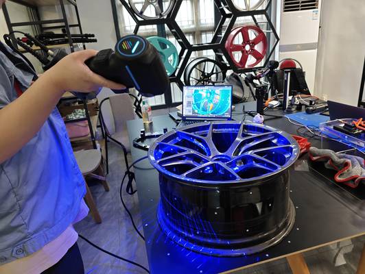
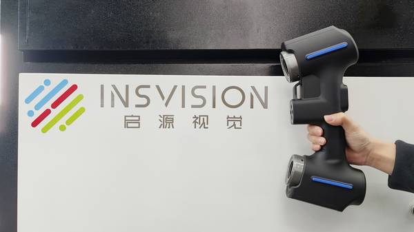
The AlphaScan handheld 3D scanner from INSVISION handles this by adjusting capture parameters on the fly, maintaining a dense point cloud across varied surface finishes without spray coating in most cases. Thin-walled aluminum investment castings pose a different set of problems, including vibration sensitivity and the tendency to flex under their own weight.
Deployment Validation Checklist
| Focus Area | Decision Point | Deployment Note |
|---|---|---|
| Target part | Check size, surface condition, and key tolerances against the scan task | Run a full trial scan on a representative part |
| Data workflow | Verify point cloud, deviation map, and quality-report handoff | Confirm export formats and review ownership in advance |
| Shop-floor use | Review training, calibration, lighting, and working space | Keep the validation record as a repeatable inspection reference |
Here, a stable fixture and a repeatable part orientation become critical; the scan path must be planned so that the part is not disturbed between the first datum alignment and the final surface capture, otherwise the datasets will shift and distort the later CAD comparison.
Practical Workflow
- Mapping the Casting’s Physical Profile Before Data Capture — Before any scan begins, the part needs to be read as a physical object.
- Inspection Challenges That Start with the Casting Process — The casting process itself introduces the most common inspection headaches.
- Building a Scan Strategy That Follows the Risk Profile — A practical scan strategy starts with a risk-based approach: identify the features most likely to fail, and make sure they are ca…
- From Scan Data to a Closed-Loop Quality Decision — The output of a casting scan is not just a point cloud;
Deep cavities and narrow internal passages deserve special attention in the object assessment. A turbine housing with a small, curved inlet neck and a large outlet scroll can trap the scanner’s field of view, requiring multiple approach angles and a stitching strategy that relies on the external geometry as a stable reference frame.
In such cases, markers placed on the outer flanges help the INSVISION system maintain global registration even when the scanner moves into areas where feature geometry is sparse or repetitive.
The goal is not to scan everything in one pass, but to build a data map that prioritizes functional surfaces—mating faces, seal grooves, bore centers—and captures adjacent blended areas with enough density to support deformation analysis.
Inspection Challenges That Start with the Casting Process
The casting process itself introduces the most common inspection headaches. Sand inclusions, mold shifts, and pattern wear create dimensional variation that can be localized to a single cavity or distributed across the entire batch. Chill zones and uneven cooling often produce a twisted parting line, especially on longer structural castings like engine block ladder frames.
The inspection task is not only to measure the part, but to separate process noise from true out-of-tolerance conditions. A point-based CMM inspection might miss a localized parting line shift because the probe points are sparse; a full-field 3D scan captures the complete surface, allowing a technician to overlay the scanned data onto the CAD model and immediately see where the mold halves have drifted relative to each other.
Surface finish and color also affect the measurement workflow. A freshly blasted ductile iron casting is generally cooperative, but a heat-treated steel casting with a dark oxide scale may benefit from a quick check of the scanner’s exposure preset.
The AlphaScan scanner’s blue laser technology and high dynamic range help maintain data integrity on these challenging surfaces, reducing the need for developer spray and the associated cleaning steps.
For foundries running first-article inspection or small batch verification, the ability to scan a part as it comes out of the finishing department—without extra surface preparation—directly shortens the time from casting to the dimensional report.
The same scanner can also be used to verify core set marks, wall thickness variation (by scanning both sides and comparing), and stock material distribution before machining, giving the CNC programmer a head start on zero-point alignment.
Building a Scan Strategy That Follows the Risk Profile
A practical scan strategy starts with a risk-based approach: identify the features most likely to fail, and make sure they are captured with the highest confidence. On a pump volute, the tongue area and the cutwater edge are critical for hydraulic performance, so the scan path should orbit those areas with some overlap and a slightly denser point spacing.
The large outer flange, which is less sensitive, can be captured with a coarser step. The handheld form factor of the AlphaScan makes it easy to walk around the part and adapt the scan density in real time, watching the on-screen point cloud fill in the zones of interest. If a section shows poor coverage, the operator can revisit that area without restarting the entire scan.
Once the raw data is captured, alignment to the CAD model is the step that reveals whether the scan strategy was successful. A best-fit alignment on the machined reference surfaces gives a quick overview of general form, while a datum-based alignment (using the primary, secondary, and tertiary datums defined on the drawing) unlocks GD&T evaluations such as profile of a surface, position, and runout.
The INSVISION software platform supports both approaches, and it allows the user to toggle between alignment modes so that the same scan dataset can be examined from a process control viewpoint and from a final inspection viewpoint.
For castings that will be machined, the scan can also be used to simulate the machining stock: by overlaying the machined CAD model on the casting scan, a machinist can see whether the part will clean up, and how much material remains on each surface. This is often more valuable than a simple pass/fail report because it enables upstream decisions on pattern repair or core box adjustment.
From Scan Data to a Closed-Loop Quality Decision
The output of a casting scan is not just a point cloud; it is a dataset that needs to feed into a quality decision. A color map deviation report is the most common deliverable: the scanned surface is colored from green to red to blue to show plus or minus material relative to the nominal CAD.
For a foundry engineering team, a repeatable pattern of excess material on a specific rib suggests that the pattern needs to be dressed, while a localized negative deviation on a boss may indicate a sand inclusion or a core that shifted and then eroded. The report can include cross-sectional views, wall thickness analyses, and whisker plots that show the direction and magnitude of deformation.
INSVISION’s software generates these reports in a format that can be shared with the customer or used internally to track process capability.
The final piece of the puzzle is the feedback loop to the pattern shop, the core room, and the pouring floor. A dimensional report that arrives three days after the casting is poured is a historical record; a report that arrives within an hour becomes a process adjustment tool.
The speed of a handheld scanning system like AlphaScan means that the foundry can inspect a first-off casting before the next mold is poured, catching a pattern shift or a core set error before it affects a whole shift’s production. When the scanning system is used consistently, the historical scan data can be trended over time, showing gradual pattern wear or seasonal effects on sand expansion.
The result is a casting inspection workflow that moves from sampling a few dimensions to understanding the entire part, and from reacting to scrap to preventing it before the metal is poured.
Hangzhou Insvision Technology Co., Ltd.
Address: Building 1, No. 1399 Liangmu Road, Yuhang District, Hangzhou, Zhejiang 311121, China