

3D scanning for automotive body panels: Object-Driven 3D Scanning Workflow
A door skin that looks fine on the rack can still pull a quarter-millimeter gap once it meets the fender. When that happens on a moving line, the cost moves fro
What Makes a Body Panel Difficult to Measure
Stamped steel and aluminum panels share a few traits that make traditional contact measurement slow and sometimes unreliable. The part is large in area but thin in section, which means it flexes under its own weight or shifts slightly on the fixture. Surfaces are often Class A, with a mix of high gloss, subtle curvature, and compound radii that blend into sharp feature lines.
A few microns of springback after forming can escape a point-based check but show up as a mismatch at the hemming station. Add to this the need to capture trim edges, pierced holes, and mounting flanges — all in one setup, often within a production-side temperature cycle — and the measurement task becomes less about individual tolerances and more about controlling the whole shape under real holding conditions.
Deployment Validation Checklist
| Focus Area | Decision Point | Deployment Note |
|---|---|---|
| Target part | Check size, surface condition, and key tolerances against the scan task | Run a full trial scan on a representative part |
| Data workflow | Verify point cloud, deviation map, and quality-report handoff | Confirm export formats and review ownership in advance |
| Shop-floor use | Review training, calibration, lighting, and working space | Keep the validation record as a repeatable inspection reference |
Scenario Snapshot
A practical way to read the article is through this scenario:
- What Makes a Body Panel Difficult to Measure: Stamped steel and aluminum panels share a few traits that make traditional contact measurement slow and sometimes…
- Matching the Scanning Strategy to the Panel: A handheld scanner like the INSVISION AlphaScan changes the workflow because it removes the need to bring the pane…
- From Point Cloud to Actionable Report: Once the scan is complete, the raw point cloud is meshed and aligned to the CAD nominal inside the inspection soft…
The material itself matters. Bare aluminum reflects light differently across grain direction; dark tooling oils or dry-film lubes can change surface response. Painted panels look uniform but can give a laser scanner fits if the clearcoat is highly specular.
Any metrology approach that ignores these surface conditions will produce noisy data right where it counts: along the mating edges and character lines that define the panel’s perceived quality.
Matching the Scanning Strategy to the Panel
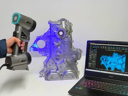
A handheld scanner like the INSVISION AlphaScan changes the workflow because it removes the need to bring the panel to a fixed measuring station. The operator can walk around a door, hood, or quarter panel while it sits on a soft fixture or a checking stand, capturing geometry from multiple angles and letting the software stitch the data into a single mesh.
The blue laser source on the AlphaScan handles common shop-floor reflectivity without coating the panel in developer spray, which saves time and avoids contaminating parts that will be painted or bonded later.
The scanning sequence usually follows the panel’s stiffness gradient. For a large hood outer, the operator might start along the centerline ridge, where the crown resists deflection, then work outward toward the hemmed edges. Targets or geometry-based tracking keep the data aligned even when the operator pauses to reposition.
Deep draws, such as the license plate pocket on a bumper fascia or the fuel-filler recess on a rear quarter, get a second pass at a steeper angle to pull enough points from the cavity floor.
The scanner’s high frame rate means that the operator can slow down over these features without losing tracking, and the point density remains high enough to resolve small radii and blend transitions that contact probes would struggle to follow.
From Point Cloud to Actionable Report
Once the scan is complete, the raw point cloud is meshed and aligned to the CAD nominal inside the inspection software. The real value shows up in the color map: a full-field deviation plot that instantly highlights where the panel is within tolerance and where it is trending toward the limit.
An engineer looking at a door inner can see at a glance whether the lock-mounting surface is flush with the surrounding plane, whether the hinge reinforcement has shifted during spot welding, and whether the hem flange is consistent around the perimeter.
For many teams, the most useful deliverable is not the 3D map itself but the cross-sectional analysis. Pulling a virtual gauge line along the A-pillar or the beltline reveals gap and flushness trends that match what the customer will see on the finished vehicle.
The INSVISION software supports direct CAD comparison, so the same scan data that checks the stamped panel can also be used to verify the fixture or to inspect the panel after trimming and piercing. Reports can be output as a PDF with user-defined pass/fail criteria, making them suitable for both internal quality gates and supplier PPAP documentation.
Because the scan captures the whole surface, it also builds a digital record of the part’s as-built condition, which can be recalled later if a field issue appears and the team needs to trace back to a specific production batch.
Building a Repeatable Process for Production
Bringing handheld 3D scanning into a production environment requires more than just a capable scanner. The most reliable programs define a standard scan path, a standard fixture that doesn’t over-constrain the part, and a set of reference features that are used to align every scan to the same coordinate system.
For body panels, alignment often relies on tooling holes or net-pad surfaces that are machined in the same operation as the outer form. Consistency here is what turns a one-off troubleshooting exercise into a process that can run every shift.
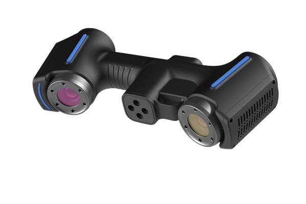
The INSVISION AlphaScan fits into this routine because it is self-contained and lightweight, with no external controller or tripod needed. An operator can pick it up, scan a panel, and have a first-pass deviation map within minutes.
Over time, the accumulated scan data reveals trends — a die that is wearing along a specific character line, a springback condition that worsens as the coil progresses, a fixture clamp that is pulling the panel slightly out of plane.
Catching these signals early, while the part is still within the tolerance band, prevents the kind of late-stage mismatch that stops a line and sends a team of engineers back to the stamping plant. The result is a quieter, more predictable launch and a panel that fits the way it was designed to fit.
Hangzhou Insvision Technology Co., Ltd.
Address: Building 1, No. 1399 Liangmu Road, Yuhang District, Hangzhou, Zhejiang 311121, China