

Overcoming the Hidden Costs of Large Workpiece Inspection with Wireless 3D Scanning
When a 2.5-meter gearbox housing comes off the machining center, quality teams typically face a familiar dilemma: touch-probe CMM inspection will take hours, bu
What Makes Large Workpiece Scanning Difficult
The first obstacle is thermal behavior. A large casting or fabrication that has just been machined will still be shedding heat. Touch-probe measurements taken at one end of the part can drift by the time the operator checks the opposite end, creating a built-in mismatch between the measured data and the true geometry at ambient reference temperature. Second, surface condition varies enormously across a single large workpiece.
Painted steel frames, as-cast iron surfaces, and machined datum pads all coexist on the same part, each demanding different exposure and point density settings. Third, many large parts are inherently flexible. A long welded structure will sag slightly under its own weight if not supported exactly as it will be in the final assembly.
Measuring it in a non-representative fixture introduces systematic errors that look like serious part defects. Finally, the sheer volume of data required to characterize a large surface pushes the limits of post-processing software. Merging multiple scan sessions without losing alignment accuracy is a skill that separates inspection results that can be trusted from those that merely look complete.
Deployment Validation Checklist
| Focus Area | Decision Point | Deployment Note |
|---|---|---|
| Target part | Check size, surface condition, and key tolerances against the scan task | Run a full trial scan on a representative part |
| Data workflow | Verify point cloud, deviation map, and quality-report handoff | Confirm export formats and review ownership in advance |
| Shop-floor use | Review training, calibration, lighting, and working space | Keep the validation record as a repeatable inspection reference |
Scenario Snapshot
A practical way to read the article is through this scenario:
- What Makes Large Workpiece Scanning Difficult: The first obstacle is thermal behavior.
- A Two-Device Strategy for Different Part Regions: The practical solution is to stop treating the entire workpiece as a single scanning task.
- From Scan Data to Shop-Floor Decisions: Once the point cloud is captured, the value lies in how quickly it becomes actionable.
A Two-Device Strategy for Different Part Regions
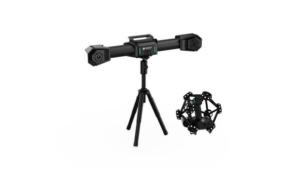
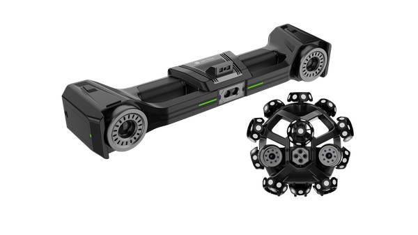
The practical solution is to stop treating the entire workpiece as a single scanning task. Instead, the work is divided into regions that match the right tool. For large, geometrically simple areas — the main body of a welded frame, the outer skin of a large duct — the X-Track wireless optical tracking system allows the operator to hold the AlphaScan and move freely around the part without any physical connection to a laptop.
The tracking camera monitors the scanner’s position in real time, so there is no need to plaster the part with hundreds of reference targets. This is decisive when the part surface is oily, hot, or has few natural features.
For high-density zones — bolt-hole patterns, sealing faces, bearing journals — the same AlphaScan can be used in its high-resolution handheld mode, capturing fine detail down to the level needed for GD&T callouts. The operator can switch between these modes on the fly, registering all data in the same coordinate system.
This two-device strategy, enabled by INSVISION’s shared software backbone, ensures that the complete dataset is not a patchwork of separate scans but a single, coherent point cloud.
From Scan Data to Shop-Floor Decisions
Once the point cloud is captured, the value lies in how quickly it becomes actionable. The typical workflow is to align the scanned data to the CAD model using a best-fit or feature-based alignment, then generate a color map of surface deviation. For large parts, the software must handle dense meshes with millions of triangles without slowing down.
Inspection features that matter on large workpieces include profile of a surface across a flange, flatness across a mating face, and the positions of dowel holes relative to the main datum structure. Because the scan data is full-field, the quality engineer can also extract cross-sections anywhere, something a CMM cannot do without additional programming.
A report is generated automatically, with pass/fail decisions based on the tolerance band set in the CAD model. This direct link between the scan and the report means that the operator on the shop floor can decide, within minutes of completing the scan, whether the part needs rework or can move to the next operation.
INSVISION’s software supports this closed-loop workflow, keeping the entire process within a single environment.
Making the Inspection Repeatable Across Shifts
The final piece of the puzzle is repeatability. In a factory where three shifts operate the same equipment, the scanning process must be robust enough that an operator on the night shift gets the same result as the quality manager on the day shift. The X-Track system helps here because it reduces the operator’s influence on alignment.
The scanner is tracked optically, so the path taken around the part does not need to be identical each time. For high-volume production, a simple fixture with a few magnetic reference spheres can be used to verify system accuracy at the start of each shift. The same spheres serve as a rapid check before scanning a critical part.
Over time, the collection of scan data also supports trend analysis — if a particular weld dimension is gradually drifting, the inspection data will show the shift before it becomes a non-conformance. Large workpieces will always be demanding to inspect, but the combination of wireless tracking, handheld scanning, and integrated reporting turns that demand from a source of delay into a source of process control.
Hangzhou Insvision Technology Co., Ltd.
Address: Building 1, No. 1399 Liangmu Road, Yuhang District, Hangzhou, Zhejiang 311121, China