

Beyond Line of Sight: Capturing Deep Hole Geometry Without Cutting Parts Open
When a fuel system manifold arrives at the quality lab, the external surfaces are straightforward to measure. A CMM, a laser scanner, even a structured light sy
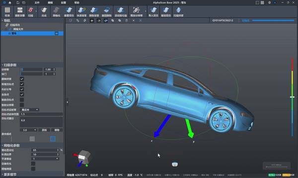
INSVISION engineers have been fielding a growing number of requests around this exact problem. The AlphaScan handheld 3D scanner, originally selected for its speed on complex external surfaces, is increasingly deployed with a mirror-based probing strategy to reach bores, cross-holes, and deep pockets that start at only a few millimeters in diameter.
The workflow does not require cutting the workpiece, pouring RTV silicone, or waiting for the replica to cure. A single operator can scan the external reference geometry, then insert a right-angle or conical mirror attachment into the internal cavity and continue capturing data in the same coordinate system.
Deployment Validation Checklist
| Focus Area | Decision Point | Deployment Note |
|---|---|---|
| Target part | Check size, surface condition, and key tolerances against the scan task | Run a full trial scan on a representative part |
| Data workflow | Verify point cloud, deviation map, and quality-report handoff | Confirm export formats and review ownership in advance |
| Shop-floor use | Review training, calibration, lighting, and working space | Keep the validation record as a repeatable inspection reference |
The scanner’s structured light pattern reflects off the mirror, illuminates the internal wall, and returns a point cloud that stitches seamlessly with the exterior scan. The part stays intact. The data comes out whole.
Internal Geometry Profiles That Create Inspection Dead Zones
Not every hole is a deep hole problem. A through-bore with a diameter of 20 mm and a length of 40 mm is trivial for a narrow CMM stylus. The difficulty escalates when the depth-to-diameter ratio climbs past 5:1, when the hole is blind, or when the internal feature includes a cross-drilling, an undercut, or a seat angle that must be verified against the CAD model.
Typical offenders include hydraulic valve bodies with intersecting galleries, aerospace fuel nozzles with swirl chambers, injection mold cooling channels with helical baffles, and electric motor housings where internal bearing bores sit behind a shoulder. The common thread is that the feature of interest cannot be seen directly from any single external vantage point. The optical path must fold.
Practical Workflow
- Internal Geometry Profiles That Create Inspection Dead Zo… — Not every hole is a deep hole problem.
- Scan Strategy and Mirror Probing for Cavities — The practical workflow starts with a quick external scan that establishes the part’s spatial reference.
- From Point Cloud to Actionable Inspection Report — The output of a mirror-assisted scan is a single fused mesh that includes both the external surfaces and the internal cavities.
- Maintaining a Closed-Loop Verification Process — Internal inspection data is most useful when it feeds back into the manufacturing process.
Surface condition inside these cavities adds another layer of difficulty. Internal bores in cast aluminum or additively manufactured parts often retain a rough as-built texture that scatters light unevenly. Oil residue, cutting fluid films, and light oxidation change the reflectivity from one region to the next.
A scanner that works well on a matte, powder-coated exterior may struggle with a semi-bright, oil-wetted internal wall unless the exposure settings and pattern intensity adapt frame by frame. The AlphaScan’s adaptive exposure loop, which adjusts laser power and camera gain on the fly, becomes relevant here.
The same hardware that handles a black carbon-fiber outer shell can recalibrate itself for the mixed reflectivity inside a cross-drilled gallery, provided the mirror optics deliver a clean projected pattern to the surface.
Scan Strategy and Mirror Probing for Cavities
The practical workflow starts with a quick external scan that establishes the part’s spatial reference. The operator places a few adhesive targets or uses the geometry’s natural features for alignment, depending on the required volumetric accuracy. Once the external envelope is captured, the scanning head is fitted with a narrow-angle mirror adapter.
The mirror extends the optical path at a 70- or 90-degree angle, allowing the structured light pattern to project sideways onto the internal wall while the scanner remains outside the hole. The operator advances the mirror in incremental steps, watching the live point cloud build on the tablet screen. Areas that show sparse data get a slower pass or a slight angle change.
The software’s real-time mesh preview makes it obvious when a section is missing, so there is no guesswork about whether the internal groove or the bottom of a blind hole has been fully captured.
The mirror itself is a consumable consideration. Repeated insertion into cast iron bores or AM parts with residual powder will eventually mar the reflective surface. INSVISION’s mirror attachments are designed as replaceable optical tips, not as permanent fixtures, which keeps the consistent cost low and avoids the slow degradation of data quality that happens when a scratched mirror stays in service too long.
For holes smaller than roughly 4 mm in diameter, the current mirror form factor reaches its physical limit, and the inspection strategy shifts to a combination of external scanning plus tactile probing on the same reference frame, or to CT scanning for the most demanding applications.
The AlphaScan does not claim to replace X-ray CT, but it eliminates the need for CT in a significant number of cases where the internal geometry is accessible through a bore entrance and the mirror can reach the feature depth.
From Point Cloud to Actionable Inspection Report
The output of a mirror-assisted scan is a single fused mesh that includes both the external surfaces and the internal cavities. The operator aligns this mesh to the nominal CAD model using a best-fit or feature-based registration, then runs a 3D comparison that generates a color map of deviations.
The areas of interest are the internal seat diameters, the intersection edges of cross-drillings, the wall thickness between adjacent galleries, and the surface profile of any internal sealing surfaces. These are precisely the features that a surface-only scan would miss entirely.
The color map reveals whether the internal bore is oversized, shifted, or tapered, and whether the cross-drilling broke through at the correct position and angle.
The reporting step is where the inspection data becomes a decision tool. The software can export deviation annotations, section views at any plane, and dimensional tables for user-defined features. For a production environment, the same scan setup and alignment can be saved as a template and applied to subsequent parts, making the internal inspection repeatable in minutes rather than hours.
The data package supplements, and in some workflows replaces, the traditional first-article inspection report that previously relied on sectioning a sacrificial part. The part that was scanned stays intact. The one that was sectioned in the old process is no longer needed.
Maintaining a Closed-Loop Verification Process
Internal inspection data is most useful when it feeds back into the manufacturing process. A scan that reveals a consistent drift in the position of a cross-drilling, for example, points to a fixture offset or a tool wear issue that can be corrected before the next batch runs. The digital twin created by the AlphaScan, combining external form and internal cavity geometry, serves as the reference for that feedback loop.
The same data set can drive a re-machining decision, a casting die adjustment, or a parameter change in an AM build file. The key is that the internal data is not a separate, hard-to-correlate dataset. It lives in the same coordinate system as the external scan, so the dimensional relationship between an internal gallery and an external mounting face is captured directly, not inferred from two disconnected measurements.
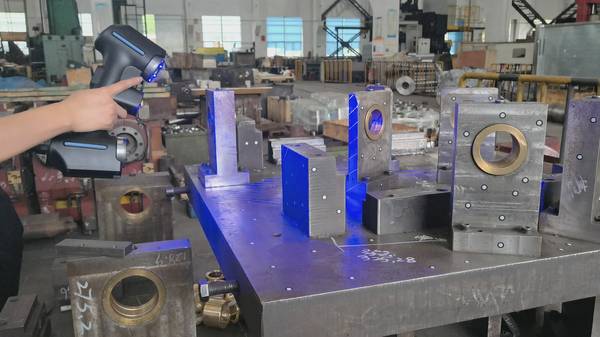
For teams that are evaluating whether to bring internal hole inspection in-house, the practical test is straightforward. Take a representative part with known internal features, scan it with the mirror setup, section it destructively, and compare the two datasets.
The correlation between the mirror-based scan and the physical section measurement, typically within a few hundredths of a millimeter depending on the depth and surface condition, answers the question definitively.
The result is a faster inspection cycle, a preserved part inventory, and a more complete geometric record of the features that actually matter to function.
Hangzhou Insvision Technology Co., Ltd.
Address: Building 1, No. 1399 Liangmu Road, Yuhang District, Hangzhou, Zhejiang 311121, China