

Precision Metrology for Complex Castings: The Case for Handheld 3D Inspection of Engine Cylinder Heads
Engine cylinder heads sit at the most unforgiving junction in the internal combustion engine. They seal the combustion chamber, carry high-pressure oil and cool
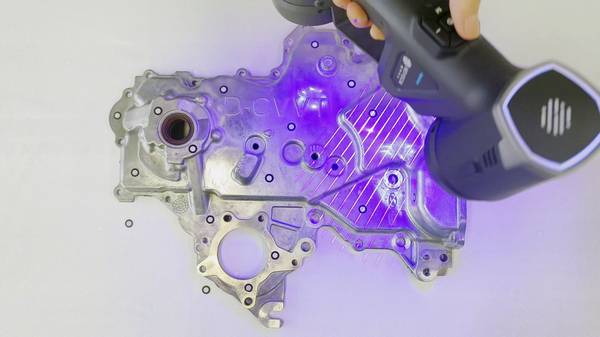
The challenge starts with the object itself. A typical foundry or machining line deals with multiple variants: diesel heads with deep injector bores, high-performance gasoline heads with reshaped port roofs, and remanufactured cores that carry unknown distortion from service cycles.
The material is usually cast aluminum or cast iron, often with as-cast surfaces that are dark, textured, and light-absorbing alongside machined gasket faces that are bright and specular. The blend of finishes on a single part means the scanning system must handle dramatic reflectance transitions without developer spray or constant recalibration. Dimensional requirements are tight.
Deployment Validation Checklist
| Focus Area | Decision Point | Deployment Note |
|---|---|---|
| Target part | Check size, surface condition, and key tolerances against the scan task | Run a full trial scan on a representative part |
| Data workflow | Verify point cloud, deviation map, and quality-report handoff | Confirm export formats and review ownership in advance |
| Shop-floor use | Review training, calibration, lighting, and working space | Keep the validation record as a repeatable inspection reference |
Valve seat concentricity, injector bore angles, port volume, and deck flatness often fall within 0.05 mm or tighter for production approval. On a reman return line, the question shifts from absolute conformance to material condition: how much stock remains, and can the part be salvaged.
What Makes Cylinder Heads Hard to Inspect
Cylinder heads combine geometric depth, optical contrast, and structural flexibility in ways that expose the limits of both contact probing and fixed-camera scanning. The combustion face is a long, narrow plane where local flatness band tolerances routinely run under 0.03 mm. The deck is surrounded by a perimeter of thin walls, bolt bosses, and coolant openings that can deform under clamping pressure.
Measuring the deck in a free state tells one story; measuring it bolted to a torque plate tells another. Both conditions matter, and the scanning workflow must accommodate both without losing coordinate reference.
Key Points at a Glance
- Cylinder heads combine geometric depth, optical contrast, and structural flexibility in ways that expose the limits of both contact probing and…
- A handheld 3D scanner such as the INSVISION AlphaScan changes the tactical equation because it is not bolted to a table.
- Raw scan data achieves nothing until it is aligned to nominal and interrogated for deviation.
- The most practical value of handheld 3D inspection for cylinder heads is not the technology itself but the speed at which it closes the loop bet…
The port side is a tangle of deeply recessed, curved passages. Valve seat rings sit at the bottom of angled bores, often 100 mm or more from the port opening. The walls inside the ports are cast surfaces that intentionally retain some roughness for flow characteristics, but they still need to be captured for volume analysis and core shift detection.
Narrow angle access, self-shadowing, and the need to resolve small features at depth place a premium on the scanner’s standoff distance, depth of field, and minimum feature resolution. On the camshaft side, the bearing journal bores and lifter pockets form a series of cylindrical datum features that must be aligned with the valve guide bores on the opposite side.
Maintaining a single coordinate system across the entire part is the metrology prerequisite for checking true position and angularity.
Building a Reliable Scan Strategy on the Shop Floor
A handheld 3D scanner such as the INSVISION AlphaScan changes the tactical equation because it is not bolted to a table. The technician can walk around the part, tilt the scanner into the intake and exhaust ports, and capture undercut regions that a fixed scanner would miss.
The AlphaScan’s structured light projector and on-board processing allow it to register geometry on the fly, even on cast aluminum surfaces that typically require coating for other optical systems. The scanner’s ability to maintain tracking on dark, textured cast iron, then transition smoothly to a bright machined deck, keeps the scan continuous and reduces the need for patch-and-stitch post-processing.
Strategy begins with datum selection. The most stable features on a cylinder head are the machined surfaces that define the engine’s mounting interface: the deck face, the dowel pin holes, and the front or rear timing cover face. A well-planned scan establishes these features first, with high point density and minimal noise, so they can serve as the alignment reference for all other data.
Once the primary datums are locked, the operator moves to the ports, the valve seats, and the oil gallery openings. The AlphaScan’s lightweight body and ergonomic grip make it practical to hold consistent angles inside deep bores for the several seconds needed to build clean point data, without arm fatigue that would translate into hand shake and data noise.
From Point Cloud to Actionable Inspection Report
Raw scan data achieves nothing until it is aligned to nominal and interrogated for deviation. The point cloud of the cylinder head is registered to the CAD model using a best-fit or datum-based alignment, depending on whether the priority is functional fit or machine-ability assessment.
For a production audit, the comparison is typically a full 3D color map overlay, where the gasket face shows a flatness gradient, the port walls show material condition, and the injector bore axis shows angular deviation. The INSVISION software environment supports direct CAD import and automatic alignment routines, which means the comparison can begin while the part is still on the bench.
The output is a report that a quality engineer can read in seconds. Deck flatness is extracted as a numerical value with a pass-fail threshold. Valve seat concentricity is shown as a deviation vector. Port volume is computed from the closed mesh.
For remanufacturing intake, the same scan data feeds a stock-on condition map: areas below minimum material are flagged red, and areas with enough stock for a re-grind are shown green. The report format is consistent across shifts and operators, which reduces the kind of interpretation drift that creeps in when different inspectors use different tools.
The data file itself is archived and can be recalled later for trending, for comparing a batch of castings from a suspect foundry lot, or for re-inspecting a feature that was not part of the original check plan.
Where the Real Payoff Shows Up
The most practical value of handheld 3D inspection for cylinder heads is not the technology itself but the speed at which it closes the loop between measurement and decision. In a machining cell, a quick scan of the first-off part in the morning can confirm that the fixture is still on location and the tool offsets are still valid after a shift change.
If the deck is trending 0.02 mm high on the exhaust side, the operator adjusts the offset before the next cycle, not after a batch of twenty parts has been machined out of tolerance. In a reman facility, the scanner becomes the triage tool. A head arrives with unknown history.
Within five minutes, the scan shows whether the seats have enough material, whether the head is warped beyond salvage, and whether the cam bore alignment is still within the rebuild spec. The decision to scrap or rework is based on measured data, not feel.
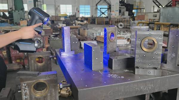
The scan data also feeds upstream into casting quality. When a pattern of core shift appears across multiple heads, the foundry can correlate the deviation with a specific mold box or core machine. The trend data is already in the system, not locked inside a single-purpose CMM report that nobody saw.
INSVISION’s approach to integrating the AlphaScan with measurement software that supports industry-standard GD&T extraction and batch statistics makes this kind of process feedback practical without a dedicated metrology programmer.
For production environments that handle cylinder heads in volume, the combination of scan mobility, optical versatility, and direct CAD comparison shifts inspection from a bottleneck to a feedback loop that runs at the speed of the line.
Hangzhou Insvision Technology Co., Ltd.
Address: Building 1, No. 1399 Liangmu Road, Yuhang District, Hangzhou, Zhejiang 311121, China