

3D Inspection of Pump Housings: Translating Complex Geometry into Actionable Quality Data
Pump housings sit at the intersection of fluid dynamics and structural integrity. A typical centrifugal pump casing blends volute contours, bearing bores, seal
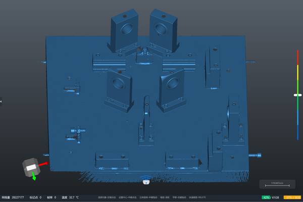
The inspection task is not just about capturing a few dimensional callouts on a drawing. Production teams need to verify that the volute scroll maintains its designed cross-sectional area, that the split-line flatness stays within tolerance, that bolt-hole patterns align with the mating casing half, and that seal grooves meet surface finish and roundness requirements.
When a housing is installed on a vibration-prone test stand or clamped in a fixture, the deformation can shift critical datums by tens of microns. In a high-mix environment where lot sizes change frequently, the inspection workflow must adapt to different pump families without excessive reprogramming.
Deployment Validation Checklist
| Focus Area | Decision Point | Deployment Note |
|---|---|---|
| Target part | Check size, surface condition, and key tolerances against the scan task | Run a full trial scan on a representative part |
| Data workflow | Verify point cloud, deviation map, and quality-report handoff | Confirm export formats and review ownership in advance |
| Shop-floor use | Review training, calibration, lighting, and working space | Keep the validation record as a repeatable inspection reference |
These conditions explain why many shops are moving beyond the CMM-sampling approach — where a handful of touch points extrapolate an entire surface — and toward full-field 3D scanning that captures the whole shape in one session.
Building a Scanning Strategy for Deep Cavities, Flanges, and Thin Walls
A handheld 3D scanner like the INSVISION AlphaScan changes the inspection equation because it can be brought to the part rather than the other way around. For a pump housing sitting on a workbench or still mounted on the machining fixture, the operator first establishes a manageable scan path.
Typically, the exterior surfaces — flanges, mounting feet, and the outer volute profile — are acquired first, using the scanner’s built-in target tracking or feature alignment. The real challenge lies inside the volute cavity and around the sealing faces.
Here, the scanner’s short standoff distance and blue-laser fringe projection help capture tight corners without excessive shadowing, but the operator still needs to tilt the device and sweep from multiple angles, letting the software stitch overlapping frames into a dense point cloud.
Scenario Snapshot
A practical way to read the article is through this scenario:
- Building a Scanning Strategy for Deep Cavities, Fla…: A handheld 3D scanner like the INSVISION AlphaScan changes the inspection equation because it can be brought to th…
- From Point Cloud to CAD Comparison: Closing the Dat…: Once the raw scan data is meshed and aligned to the nominal CAD model, the real value of 3D inspection emerges.
- What to Look for When Bringing Handheld 3D Scanning…: Putting a handheld scanner into a pump housing inspection cell requires alignment between the tool’s capabilities…
Certain surface conditions demand extra care. Raw cast iron housings with a mottled, as-cast texture scatter light unevenly; polished stainless steel or aluminum can produce reflections that confuse lower-end scanners. The INSVISION AlphaScan is designed to handle these mixed surfaces with minimal preparation, reducing the reliance on sprays or coatings that add cleanup steps and can mask fine detail.
For deep bolt holes and threaded inserts, the scanning protocol may include a few targeted passes with a probing attachment or a structured light burst at a different exposure setting. Throughout the process, the live preview on the connected tablet gives the operator immediate feedback on coverage — missing data patches show up in real time, so the scan can be adjusted before the part is moved.
This iterative sweep-and-verify approach cuts down the risk of discovering blind spots later during offline analysis.
From Point Cloud to CAD Comparison: Closing the Data Loop
Once the raw scan data is meshed and aligned to the nominal CAD model, the real value of 3D inspection emerges. The software overlays a color map directly onto the 3D model, painting the pump housing in gradients from green to red and blue to indicate positive or negative deviation from design intent.
For a volute housing, the engineering team can scroll through cross-sections, checking that the throat area and diffuser transition zones stay within the tolerance band. The same dataset also serves additional checks: flatness of the mounting flange, concentricity of the bearing bore relative to the seal bore, and angularity of the discharge nozzle.
Instead of generating separate inspection reports for each characteristic, a single aligned scan feeds into a unified report that can be customized with pass/fail criteria, statistical summaries, and annotated screenshots.
The data loop does not end with a report. In many pump manufacturing workflows, the scan results feed back into the machining process. If a trend of wall thinning appears on the impeller side of the volute, the production team can adjust core placement or machining offsets before the next batch of castings arrives.
For rework decisions, the scan helps distinguish between recoverable deviations and those that require scrapping the part. INSVISION’s software environment supports exporting the deviation data into common formats for statistical process control, so inspection data becomes a continuous improvement asset rather than an isolated quality gate.
And because the AlphaScan stores the full geometry, not just a few measured points, the same file can be revisited months later if a field failure investigation demands a detailed look at the as-built shape.
What to Look for When Bringing Handheld 3D Scanning into Pump Production
Putting a handheld scanner into a pump housing inspection cell requires alignment between the tool’s capabilities and the production environment. Accuracy is an obvious screening criterion; for pump housings, the scanner should demonstrate volumetric accuracy in the range of tens of microns, ideally verified against a certified artifact traceable to a national metrology institute.
The INSVISION AlphaScan, backed by a quality management system that includes ISO 9001 and CNAS-recognized calibration, is built to meet this threshold. Equally important is how the scanner performs on the materials and surface finishes that dominate the shop’s product mix.
A tool that struggles with glossy machined faces or dark cast iron without surface preparation will create bottlenecks that cancel out the speed gains of scanning.
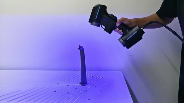
Field experience shows that ease of alignment and software workflow often determine whether a scanner gets adopted or ends up on a shelf. The operator should be able to register scans without manually sticking hundreds of targets on the part, and the software should handle partial scans of incomplete assemblies gracefully.
Support for importing multiple CAD formats and templates for recurring report layouts also matters when the inspection station serves several pump models. Ultimately, the decision should be based on a test run with a real housing — evaluating not just the point cloud quality but the total time from first scan to final report.
When the tool, the part, and the workflow match, 3D inspection of pump housings shifts from a quality bottleneck into a reliable source of dimensional intelligence that strengthens both the machining process and the customer’s confidence in the product.
Hangzhou Insvision Technology Co., Ltd.
Address: Building 1, No. 1399 Liangmu Road, Yuhang District, Hangzhou, Zhejiang 311121, China
Copyright © Hangzhou Insvision Technology Co., Ltd. All rights reserved.
Copyright © Hangzhou Insvision Technology Co., Ltd. All rights reserved.