

What Makes 3D inspection of thin sheet metal parts Difficult to Capture Accurately
Measuring a rigid steel block is straightforward. The part sits still, the coordinate measuring machine registers stable points, and the GD&T report prints with

Thin sheet metal components appear everywhere in modern manufacturing: EV busbar carriers, heat exchanger fins, stamped chassis brackets, and fuel cell separator plates. Their common thread is a thickness-to-area ratio that makes them mechanically compliant. A 300 mm stamped cover with a 0.5 mm wall can deflect 200 microns under a standard touch probe, which is often larger than the part tolerance itself.
Surface finish adds another layer of difficulty. Stamped and hydroformed parts frequently arrive with light oil films, mill scale, or low-reflectivity zinc coatings. Laser scanners that rely on consistent return signals can struggle with these variable surfaces, generating noisy point clouds along embossed ribs and drawn edges where the material has thinned.
Deployment Validation Checklist
| Focus Area | Decision Point | Deployment Note |
|---|---|---|
| Target part | Check size, surface condition, and key tolerances against the scan task | Run a full trial scan on a representative part |
| Data workflow | Verify point cloud, deviation map, and quality-report handoff | Confirm export formats and review ownership in advance |
| Shop-floor use | Review training, calibration, lighting, and working space | Keep the validation record as a repeatable inspection reference |
The INSVISION AlphaScan handheld 3D scanner addresses these challenges through a combination of blue laser projection and high-dynamic-range imaging that adapts exposure on the fly. When scanning a deep-drawn tray with vertical sidewalls and a textured bottom surface, the scanner adjusts per-frame parameters to hold dense data on the rim while maintaining accuracy through the darker, oil-coated floor.
Because the scanner is handheld, the operator can rotate around the part on a granite or composite inspection table, capturing springback-prone flanges in their free state without clamping. This free-state data is what the designer actually needs to validate—not the forced-flat geometry a fixture imposes.
Understanding How Thin Parts Misbehave Before Measurement
Springback is the defining metrology problem for thin sheet metal. A stamped rib that looks straight to the eye may have relaxed 0.15 mm after leaving the die, and that deviation is frequently concentrated in narrow transition zones where the bend radius meets the flat web. Contact methods smear this information across probe tip radius compensation.
Non-contact optical methods preserve it, but only if the sensor can resolve the local curvature with enough point density. Thin sections also exhibit thermal sensitivity. A part transported from a press shop at 35°C to a quality lab at 22°C can shift by tens of microns within minutes.
The practical implication is that single-point measurements on a CMM, taken sequentially over 20 minutes, can reflect thermal drift as much as actual form error.
Scenario Snapshot
A practical way to read the article is through this scenario:
- Understanding How Thin Parts Misbehave Before Measu…: Springback is the defining metrology problem for thin sheet metal.
- Building a Scan Strategy Around the Geometry, Not t…: A fixture-first inspection approach assumes the part is rigid, which thin sheet metal parts are not.
- From Point Cloud to Actionable Report in a Producti…: Data processing for thin sheet metal must handle one persistent annoyance: the parts are rarely perfectly flat, an…
Surface condition interacts with material thickness in ways that confuse traditional inspection sequencing. A hydroformed aluminum heat shield with a matte, as-etched surface scatters blue light differently than a polished stainless steel deep-drawn cup.
The AlphaScan handles this by capturing multiple exposures per scan line, effectively building a composite image that retains data on both bright and dark regions within a single pass. This matters most on features like shallow embossments and stiffening beads, where the transition shoulder is often the critical zone for fatigue and crack initiation.
Losing 15 mm of a bead profile because of a surface reflection artifact turns a passing part into a false negative, or worse, a false positive.
Building a Scan Strategy Around the Geometry, Not the Fixture
A fixture-first inspection approach assumes the part is rigid, which thin sheet metal parts are not. A more reliable sequence starts with free-state scanning of the part resting on three datum points, followed by a virtual fixture alignment in software. The operator scans the entire visible surface, then flips the part to capture the reverse side.
The AlphaScan software merges the two sides using target-based or feature-based alignment, producing a single 3D dataset that represents the as-manufactured condition. This double-sided merge is especially important for parts with pierced holes and slots, where burr direction and die clearance affect the true hole diameter and position.
The scan path itself is object-driven. For a long narrow busbar with a Z-bend in the middle, the operator moves longitudinally along the flat sections, then spirals around the bend zone to capture the transitional geometry at higher density. Edges and trim lines—often the datums for assembly fit—require a deliberate pass with the scanner angled to collect both the top surface and the sheared edge profile.
INSVISION’s software then generates a mesh with sufficient resolution to extract a virtual edge line, which can be compared directly to the CAD nominal. This eliminates the need for a physical edge finder or a profile projector, collapsing what used to be a separate optical comparator step into the same 3D scanning workflow.
From Point Cloud to Actionable Report in a Production Cadence
Data processing for thin sheet metal must handle one persistent annoyance: the parts are rarely perfectly flat, and the CAD model is often a mid-plane idealization. The alignment step therefore requires care. A best-fit alignment across the entire surface can mask a localized springback deviation by distributing error across the part.
A better approach uses a datum reference frame derived from the functional assembly datums—typically the bolt holes, edge locators, or surface pads that define how the part sits in the next welding or assembly station. The AlphaScan system supports datum-based alignment, so the color map report directly reflects how the part will present itself in the assembly fixture, not just how it compares to an idealized global shape.
Report generation must match the pace of production. A stamping line producing 400 parts per shift cannot wait for a half-day CMM report. The scan-to-report pipeline for a typical thin sheet metal part—scan both sides, align to datum, run GD&T analysis, and export a color-map PDF—takes minutes rather than hours.
The output includes surface deviation maps, edge trim line deviation, hole position tables, and thickness analysis at critical sections. For ongoing process control, the same scan data can be stored and compared longitudinally, tracking tool wear trends across thousands of hits.
When a die begins to show consistent springback drift in a specific corner, the trend shows up in the scan data before the parts fall out of tolerance.
Where Non-Contact Inspection Proves Its Value Across the Shop Floor
The strongest argument for adopting handheld 3D scanning on thin sheet metal parts is not accuracy in isolation—it is the removal of inspection-induced variability. Two technicians measuring the same flexible part with a height gauge and a surface plate will often report different numbers because they preload the part differently. The scanner removes that variable.
It also opens up inspection locations that were previously impractical. A quality engineer can scan a part directly at the press line, on a vibration-damped cart, using the part’s own weight as the fixturing force. This is not a controlled lab environment, but thin sheet metal parts do not need a granite tomb—they need a measurement method that respects their flexibility.
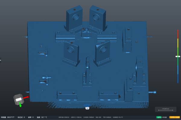
INSVISION, an AI-driven metrology-grade 3D vision technology provider headquartered in Hangzhou, has built the AlphaScan handheld scanner with this exact philosophy. The system holds CE, FCC, and CNAS-recognized certifications, and its software includes PTB-validated algorithms that give confidence in the reported numbers without requiring an external metrology package.
For quality managers overseeing stamping, hydroforming, or laser-cut sheet metal production, the practical question is straightforward: can the tool capture the true free-state shape of a thin, flexible part, and can it do so repeatably across shifts.
The AlphaScan answers that question by delivering dense, full-field data in a workflow that operators can learn quickly, and by producing reports that engineers can trust to make tooling decisions.
Hangzhou Insvision Technology Co., Ltd.
Address: Building 1, No. 1399 Liangmu Road, Yuhang District, Hangzhou, Zhejiang 311121, China