

When Narrow Gaps Defeat Standard Inspection Tools
A turbine disk with cooling channels no wider than a fingernail. A fuel injector body where the critical sealing surface sits 60 mm below the entry face. An add
Standard laser scanners lose line of sight once
Standard laser scanners lose line-of-sight once the gap drops below a certain width-to-depth ratio. Hard probes on CMMs often cannot physically enter the feature at all, and even when they can, the stylus diameter limits the smallest internal radius that can be traced. Replication compounds and silicone casts add hours of handling time and introduce their own shrinkage uncertainty.
The result is a routine acceptance decision made on incomplete data, or a concession that hands over risk to the assembly stage. The question is not whether the gap is hard to reach; the question is whether the inspection strategy is designed for the geometry or borrowed from a flat-surface workflow.
Capability and Deployment Mapping
| Focus Area | Decision Point | Deployment Note |
|---|---|---|
| Standard laser scanners lose line of sight once | Standard laser scanners lose line-of-sight once the gap drops below a certain width-to-depth ratio. | Hard probes on CMMs often cannot physically enter the feature at all, and even when they can, the stylus diameter limits the smallest internal r… |
| The material amplifies every one of these problems | The material amplifies every one of these problems. | Machined aluminum and nickel alloys inside aero-engine components are bright and specular; |
| The scan data flows into a software environment | The scan data flows into a software environment where the cavity surface is aligned to the nominal CAD model. | A cylindrical or planar best-fit registration locks the internal geometry to the global coordinate system, and a surface comparison map highligh… |
| The through line from a narrow gap scan | The through-line from a narrow-gap scan to a reliable inspection report runs through operator consistency. | A cavity that is scanned once by a skilled technician and again by a trainee must produce the same dimensional output. |
Tight clearances create a chain of measurement problems that start long before the scan trigger is pressed. The first issue is access: the scanner head must get close enough to project structured light onto the target surface and recover a clean return signal. In a narrow gap, the projector and the camera sit at different angles, and the depth shadow from one side of the cavity can occlude the view from the other.
The second issue is multi-bounce reflection. When light enters a metallic slot, it ricochets between the walls, producing false points and ghost geometry in the point cloud. The third issue is reference. A deep cavity often lacks stable surrounding surfaces for alignment, so the scanner must rely on the few visible edges or on fiducial targets placed at the mouth of the feature.
The fourth issue is validation: without a trustworthy independent measurement inside the gap, the scan data itself is hard to verify.
The material amplifies every one of these problems
The material amplifies every one of these problems. Machined aluminum and nickel alloys inside aero-engine components are bright and specular; stray reflections can push noise levels above the tolerance band. Dark, oxidized cast iron in a hydraulic manifold absorbs light and demands high dynamic range from the sensor.
Thin-walled structures, such as the web between two adjacent slots in a bracket, vibrate under the pressure of a touch probe but remain stable during non-contact optical capture. Each material choice forces a decision about exposure time, projection pattern, and whether the scan needs to be performed from one side, both sides, or at multiple angles stitched together.
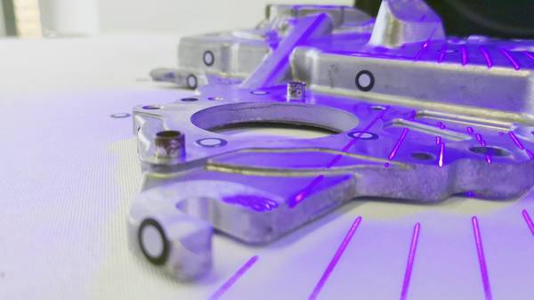
Cadenced inspection of narrow-gap features calls for a workflow that treats the cavity as the primary subject, not a secondary afterthought. A handheld scanner built around blue laser projection and compact optics can enter a tight space at an oblique angle while still maintaining a triangulation baseline wide enough to hold volumetric accuracy.
The INSVISION AlphaScan, for instance, uses a narrow-form scanning head that reaches into slots and grooves where a bulkier device would bottom out. The scanner projects a fine fringe pattern across the cavity floor and walls, and a single pass captures the full cross-section without requiring the operator to fan the device through an arc.
The field of view is constrained by the gap width, but the scan rate keeps point density high enough for a stable mesh even when the visible area is only a few square centimeters.
The scan data flows into a software environment
The scan data flows into a software environment where the cavity surface is aligned to the nominal CAD model. A cylindrical or planar best-fit registration locks the internal geometry to the global coordinate system, and a surface comparison map highlights deviation across the depth of the feature.
The color map answers the question that dial indicators and bore gauges cannot: where exactly along the wall does the profile drift out of tolerance, and is the error consistent from one side of the gap to the other. The same software generates a dimensional report that calls out GD&T evaluations for the internal width, parallelism, straightness, and the blend radius at the root of the slot.
If the scan reveals a systematic offset, the data can be fed back to the machining center for a tool offset correction before the next part is cut.
Selecting a scanner for narrow-gap inspection means evaluating the geometry first and the datasheet second. A useful specification is not just the volumetric accuracy at a reference distance, but the stand-off distance and the angle of acceptance that allow the device to look into a recessed feature without losing tracking.
Field depth matters: a scanner that can hold focus across a 100 mm deep cavity while maintaining single-digit micron repeatability is more valuable than a shorter-range system with a higher headline accuracy that cannot reach the bottom of the gap.
Equally important is the software’s ability to merge narrow-field scans into a continuous mesh without introducing layer shift or scale drift, especially when the visible surface is a thin strip of data with no surrounding geometry to anchor the stitching.
The through line from a narrow gap scan
The through-line from a narrow-gap scan to a reliable inspection report runs through operator consistency. A cavity that is scanned once by a skilled technician and again by a trainee must produce the same dimensional output.
Scanner firmware that handles exposure and gain automatically, and a workflow that locks the alignment strategy to the CAD model rather than to an arbitrary first scan, reduce the variation that comes from individual judgment. Verification can be strengthened by scanning a calibrated artifact with a known internal slot width before the production run, confirming that the system reports the true value inside the feature.
That step turns a measurement claim into a traceable check.
Narrow gaps are unforgiving but they are also
Narrow gaps are unforgiving, but they are also predictable when the inspection tool is matched to the geometry. The INSVISION AlphaScan addresses the core problem—access—by putting a compact blue laser scanner head directly into the cavity, and it supports the downstream data chain with software that turns a partial view into a full dimensional report.
The result is a measurement process that treats internal features as first-class geometry, not as exceptions to be noted on a deviation report. For manufacturers whose part quality hinges on what lies between two close walls, that is the difference between knowing the number and guessing at it.
Hangzhou Insvision Technology Co.,Ltd.
Address: Building 1, No. 1399 Liangmu Road, Yuhang District, Hangzhou, Zhejiang 311121, China