

Overcoming Distortion in Large Welded Fabrications: A 3D Scanning Strategy for Heavy Structures
The geometry of a large welded structure rarely matches the design intent exactly. Even with controlled welding procedures, heat input causes localized expansio
Object Profile and Inspection Difficulties
Large welded structures present a mix of material conditions that complicate dimensional inspection. The base steel is often hot-rolled and mill scale remains on the surface, creating a dark, matte, and occasionally flaking texture that scatters laser light unpredictably. In some cases, primer coats or light rust further alter surface reflectivity.
Welds themselves introduce irregular beads, spatter, and undercuts that break the smoothness of the scanned surface. The overall size of these assemblies — frequently exceeding five meters in length and width — makes fixed coordinate measuring machines impractical, and the sheer weight rules out moving the part to a dedicated metrology lab.
Distortion from welding also means that simple cross-sectional measurements are insufficient; the entire volume must be captured to understand how the part has twisted, bowed, or shrunk. Operators need to assess flatness, squareness, hole positions, and flange alignment simultaneously, often with a tight tolerance band that requires a volumetric accuracy down to a few tenths of a millimeter.
Deployment Validation Checklist
| Focus Area | Decision Point | Deployment Note |
|---|---|---|
| Target part | Check size, surface condition, and key tolerances against the scan task | Run a full trial scan on a representative part |
| Data workflow | Verify point cloud, deviation map, and quality-report handoff | Confirm export formats and review ownership in advance |
| Shop-floor use | Review training, calibration, lighting, and working space | Keep the validation record as a repeatable inspection reference |
Practical Workflow
- Object Profile and Inspection Difficulties — Large welded structures present a mix of material conditions that complicate dimensional inspection.
- Scan Strategy and Path Planning — Capturing a complete dataset on a large welded structure requires a deliberate scan path, not just a random walk.
- Data Processing and Reporting Closure — Once the point cloud is acquired, the processing pipeline converts raw data into a deviation analysis and a set of dimensional re…
- Selection Guidance and Validation Steps — When evaluating a 3D scanning system for large welded structures, the primary validation should focus on volumetric accuracy on r…
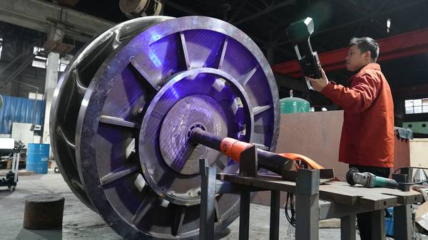
The inspection environment is another factor. Many heavy fabrication bays are not temperature-controlled, and the part itself may still be warm from welding. Any scanning system deployed here must be portable, resistant to vibration, and stable enough to maintain registration accuracy without a massive reference fixture. The X-Track wireless optical tracking system provides a strong solution for this scenario.
Instead of relying on stickers or photogrammetry targets placed over the entire structure, X-Track uses a dynamic reference frame that continuously tracks the scanner’s position from a distance. This means the operator can walk around the assembly, scan from multiple angles, and cover deep stiffener pockets or flange transitions without losing alignment.
The AlphaScan handheld scanner, with its blue laser technology, handles the dark and oxidized surfaces better than many red-laser alternatives, capturing weld profiles and mill scale directly without needing developer spray.
Scan Strategy and Path Planning
Capturing a complete dataset on a large welded structure requires a deliberate scan path, not just a random walk. The key is to control accumulated error and ensure that all functional features are captured with sufficient point density. The workflow typically starts with a quick alignment pass using the X-Track system.
The operator establishes a global coordinate system by placing a few reference targets or by using the part’s own fiducial features, such as drilled holes or machined edges. After that, the AlphaScan is moved along the primary structural members — longitudinal stiffeners, transverse frames, and main plates — with overlapping passes that maintain about 30% overlap between adjacent swaths.
For deep pockets where the scanner’s line of sight is limited, the X-Track tracker can be repositioned or additional scanning from inside the cavity can be performed; the software stitches the data automatically because the tracker maintains the same world coordinate frame.
One difficulty with welded assemblies is the presence of thin, unsupported edges and flanges that can vibrate if the scanner is moved too fast. The operator reduces scan speed around these features and uses the software’s live deviation map to verify that edge points are not smeared.
On large flat surfaces, the scanner’s built-in structure light mode can be used to capture broader areas quickly, while the laser lines are reserved for the weld toes and heat-affected zones. The combination of these modes within a single scan session keeps the overall time manageable.
For a steel module frame roughly eight meters by three meters, a complete scan with the AlphaScan and X-Track setup can be completed in under two hours, including the data processing time. The result is a dense point cloud that faithfully represents the as-built condition, including the waviness of web plates and the exact radius of welded corners.
Data Processing and Reporting Closure
Once the point cloud is acquired, the processing pipeline converts raw data into a deviation analysis and a set of dimensional reports. The alignment step uses best-fit or feature-based methods to map the scanned data onto the CAD model.
For welded structures, the preferred approach is often a localized best-fit that aligns by primary datum features — such as a machined mounting surface or a set of bolt holes — rather than a global best-fit that could distribute error across the entire part.
This mirrors the functional assembly conditions: if the part will be bolted to a mating structure, the inspection should evaluate how the rest of the part deviates relative to those interface points. The software generates a color map that highlights areas of excess material or insufficient deposition, guiding welders and fitters to the exact locations that need rework.
The reporting step is where the inspection program ties back to the quality system. Each report can include pass/fail criteria based on the customer’s drawing tolerances, statistical summaries of deviations, and annotated screenshots of critical areas. The data is stored in a format that allows traceability;
if a part is repaired and re-scanned later, the new scan can be compared to the original to verify that the correction was effective. INSVISION’s software platform supports these iterative workflows, and the wireless nature of the X-Track system means that the scan data can be uploaded to a server on the shop floor immediately, without tethering cables to a workstation.
For fabricators that need to maintain a digital twin of each serial-numbered assembly, this closed-loop approach ensures that the as-built record is always available for downstream assembly, finite element analysis, or lifecycle management.
Selection Guidance and Validation Steps
When evaluating a 3D scanning system for large welded structures, the primary validation should focus on volumetric accuracy on representative materials, not just on calibration artifacts. A practical on-site test involves scanning a known welded assembly of similar size and surface condition, then verifying the results with a laser tracker or a calibrated scale bar at several locations.
The system’s ability to maintain registration without a dense grid of targets should be tested by deliberately moving the tracker and checking that the point cloud does not shift. The software’s deviation analysis tools should be assessed for how well they handle weld bead exclusion and edge trimming, since these are common manual cleanup steps that can affect the reported dimensions.
INSVISION’s AlphaScan and X-Track combination has been designed for these heavy-industry conditions, with certifications including CE, FCC, and CNAS L2865 that support its use in regulated quality environments. The environmental durability of the system — resistance to dust, ambient light, and temperature swings — is also a factor that can be verified by running a scan in the actual fabrication bay rather than a clean lab.
Beyond the equipment itself, the integration into the fabricator’s existing workflow determines whether the investment pays off. The system should allow operators with minimal metrology training to perform scans following a predefined checklist, and the data output should plug directly into the company’s quality management software.
For large welded structures, the ability to capture the entire geometry in one session and generate a closed-loop report that feeds back to the fitting and welding stations is what transforms 3D scanning from a one-off inspection tool into a continuous improvement mechanism.
This approach reduces the risk of shipping a distorted assembly and gives production managers the confidence that every weldment meets the dimensional requirements before it leaves the shop floor.
Hangzhou Insvision Technology Co.,Ltd.
Address: Building 1, No. 1399 Liangmu Road, Yuhang District, Hangzhou, Zhejiang 311121, China