

Recovering Lost Tooling Data with Scan-to-3D in Automotive Manufacturing
A quiet but persistent problem haunts automotive supply chains: tooling that outlasts its own design data.
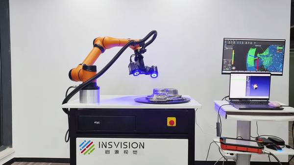
A quiet but persistent problem haunts automotive supply chains: tooling that outlasts its own design data. Injection molds, trim dies, and assembly fixtures built 15 or 20 years ago continue to run production long after the original CAD models have disappeared—lost to data migrations, supplier transitions, or simply the passage of time.
When a mold insert wears out or a legacy bracket needs a design revision, engineering teams are left holding a physical part and a deadline. Traditional metrology tools—height gauges, calipers, coordinate measuring machines—can capture discrete dimensions, but they stumble on the complex freeform surfaces, deep pockets, and subtle draft angles that define these components.
Deployment Validation Checklist
| Focus Area | Decision Point | Deployment Note |
|---|---|---|
| Target part | Check size, surface condition, and key tolerances against the scan task | Run a full trial scan on a representative part |
| Data workflow | Verify point cloud, deviation map, and quality-report handoff | Confirm export formats and review ownership in advance |
| Shop-floor use | Review training, calibration, lighting, and working space | Keep the validation record as a repeatable inspection reference |
The result is a slow, iterative loop of manual measurement, interpretation, and repeated prototyping that delays tooling repairs and threatens line stoppages.
For a tier-two supplier of interior trim components, the trigger was a worn injection mold insert. The original tooling data was gone. The insert combined glossy curved surfaces, narrow ribs, and deep recesses that made tactile or optical measurement extremely difficult. The engineering team needed a complete digital model to program a replacement electrode for EDM—and they needed it fast enough to keep the line running.
The Data Gap and How Handheld 3D Scanning Closes It
A scan-to-3D approach changes the equation by capturing the entire part as a dense point cloud in a fraction of the time manual methods require. Instead of measuring a few dozen discrete points, the scanner records millions of surface coordinates, preserving the actual as-built geometry—including wear, deformation, and the subtle contour transitions that matter for fit and function.
This is especially important when the goal is not simply to replicate a part, but to understand how it has changed in service and to make informed engineering decisions about the replacement.
The INSVISION AlphaScan handheld 3D scanner was selected for this job because its multi-line blue laser configuration handles shiny, dark, and mixed-reflectivity surfaces without spraying or coating the part. Cross-line modes cover large areas quickly, while a single blue laser line reaches into deep ribs and narrow recesses that would otherwise remain invisible.
A fine-scan mode captures delicate surface details such as texture grain boundaries and small radii, giving the reverse engineering process a complete picture of the part.
From Physical Part to Parametric Model: A Practical Workflow
The on-site work started with the mold insert still mounted on the bench. No special fixturing was required. The operator held the AlphaScan and swept across the surface, watching the live point cloud build on the screen. Areas with steep draft angles and glossy finish were captured by letting the scanner’s automatic exposure adjustment handle the varying reflectivity.
Deep pockets were addressed by switching to the single-line mode and tilting the scanner to reach the bottom corners. The entire data capture, including multiple passes for coverage verification, took less than twenty minutes.
Processing happened inside 3D INSVISION, the integrated software platform that handles alignment, noise filtering, and mesh generation. The raw scans were aligned using geometric features on the part—not targets—preserving the natural reference frame. After meshing, the model was exported to a CAD environment where the engineering team reconstructed parametric surfaces over the scanned data.
The resulting solid model was used to design the new electrode. A first-article inspection scan later confirmed that the replacement insert matched the intended geometry within the required tolerance band.
How the INSVISION AlphaScan Matches This Scenario
The AlphaScan’s combination of scan modes and blue laser technology addresses the three variables that most often derail handheld scanning on production tooling: surface reflectivity, feature depth, and the need for both speed and detail.
The scanner’s ability to switch between cross-line, single-line, and fine-scan modes in the same session means an operator can capture a glossy, curved mold surface and then immediately probe a deep rib without changing equipment or applying developer spray.
This single-device flexibility eliminates the common trade-off between coverage speed and access to tight geometries, making the AlphaScan a practical fit for tooling shops that handle a mix of part geometries and materials.
Observable Impact on the Reverse Engineering Process
While every shop’s baseline is different, several qualitative improvements emerge consistently when a scan-to-3D workflow replaces manual measurement for lost-tooling recovery:
- Reduced interpretation risk. A dense point cloud removes the guesswork involved in connecting sparse CMM points to reconstruct a smooth surface. The as-built shape is captured directly, not inferred.
- Faster handoff to design. The mesh exports directly into CAD, allowing the engineering team to begin parametric modeling within hours rather than days.
- Fewer prototype iterations. Because the scanned model reflects the actual worn geometry, the first replacement part is more likely to fit correctly, reducing the trial-and-error cycles that often plague legacy tooling repairs.
- Documentation of in-service change. The scan captures wear patterns and deformation that can inform future tooling maintenance intervals or design improvements.
Extending the Approach to Other Manufacturing Scenarios
This scan-to-3D workflow is not limited to lost tooling. The same principles apply whenever a physical object needs to become a reliable digital asset. Small mechanical components with intricate features, castings that require machining allowance verification, and worn parts that need wear-pattern documentation all benefit from the speed and surface coverage of handheld laser scanning.
In each case, the value comes from replacing sparse point measurements with a dense, full-field dataset that reduces interpretation errors and shortens the path from physical part to actionable CAD.
For quality and manufacturing engineers evaluating whether to bring scanning in-house, the key considerations are surface complexity, reflectivity, and the depth of features that must be captured.
A scanner that can handle shiny and dark surfaces without preparation, and that offers multiple scan modes to address both broad surfaces and deep recesses, will cover the widest range of reverse engineering and inspection tasks with a single device.
The result is a faster turnaround on reverse engineering requests and a more confident handoff between metrology and design—without the iterative delays that traditional methods impose.
Hangzhou Insvision Technology Co.,Ltd.
Address: Building 1, No. 1399 Liangmu Road, Yuhang District, Hangzhou, Zhejiang 311121, China