
What Manufacturers Should Check Before Choosing 3D scanning of objects
In a conventional dimensional inspection workflow, a cast housing or a machined component follows a rigid path.
Typical Workflows and Core Pain Points
In a conventional dimensional inspection workflow, a cast housing or a machined component follows a rigid path. A CMM programmer writes a touch-probe routine, a setup technician fixtures the part on a granite table, and a quality engineer waits for a report that covers perhaps 40 discrete points. The rest of the surface remains invisible.
Manual tools like calipers and height gages add operator variability, while 2D photogrammetry captures more points but delivers no true 3D deviation map against CAD. Shiny, dark, or transparent surfaces cause dropouts, and deep pockets or blind holes force rework with manual touch-probe fill-in.
These bottlenecks multiply when parts cannot be moved. An aerospace MRO team inspecting a landing gear component in a hangar, or a power generation crew scanning installed equipment, cannot rely on a fixed CMM enclosure. Transporting parts to a lab disrupts takt time and adds non-value-added hours.
Even in a well-equipped plant, the delay between part production and inspection data creates a risk: scrap can accumulate before a trend is spotted.
Solution Design: How AlphaScan Addresses the Gaps
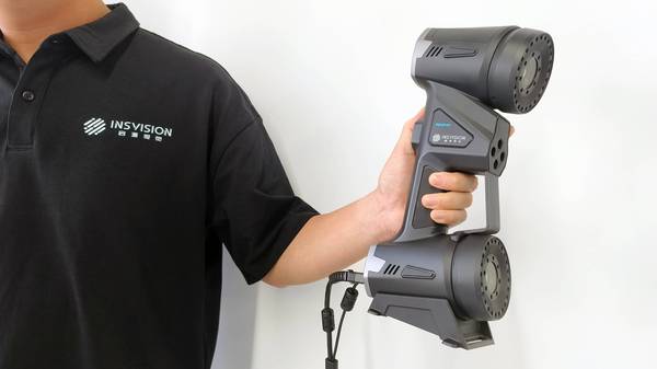
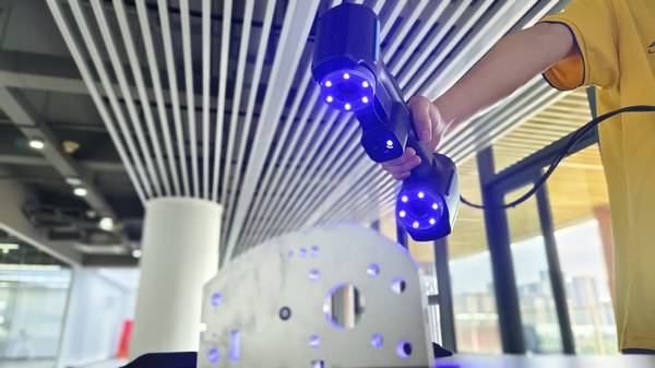
INSVISION’s AlphaScan is built to turn these high-friction 3D scanning of objects tasks into repeatable, data-clear workflows. The system captures up to 650 mm × 550 mm per single scan frame using multi-line blue laser cross patterns.
Onboard AI-enhanced point cloud logic classifies surface types on the fly—differentiating machined edges from cast textures, suppressing reflections from polished tooling, and preserving sharp feature lines that matter for ASME Y14.5 profile and position checks.
Three selectable scan modes (standard, deep-hole, and fine) let an operator switch from broad area coverage to resolving internal pocket geometry without swapping hardware.
Two engineering choices directly target common failure points. A dual LED optical layout fires from opposite sides of the lens, flooding recessed features with light so the sensor sees into pockets that single-source scanners miss. A locking USB connection uses a threaded collar that physically secures the cable to the scanner body, eliminating intermittent disconnects and data gaps in vibration-heavy environments.
Metrology-grade stability comes from a combination of inertial sensing and continuous self-calibration routines, maintaining volumetric accuracy traceable to ISO 10360 acceptance tests. Every unit ships with a factory calibration certificate—no warm-up, no user adjustment—and carries CE, FCC, and CNAS certifications, so the same device can be deployed across plants in Germany, Japan, or Mexico without requalification.
Implementation Process: From Scan to Report
Deploying AlphaScan on a production floor or in a field MRO setting follows a straightforward sequence that replaces the traditional CMM queue.
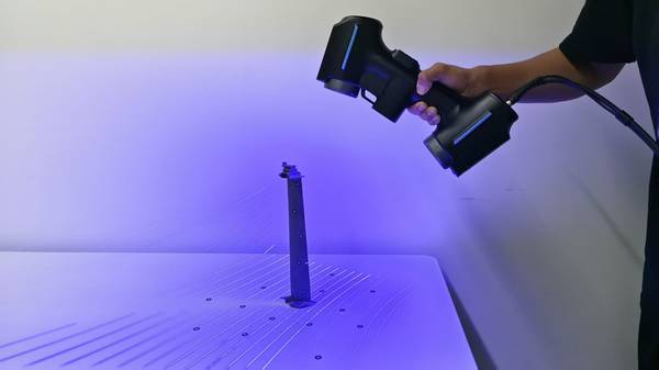
- Preparation. The operator positions the part on a stable surface—no fixture, no tripod, no external tracking targets. The scanner connects to a laptop running INSVISION’s 3D software ecosystem. The locking USB collar clicks home, ensuring a secure data link.
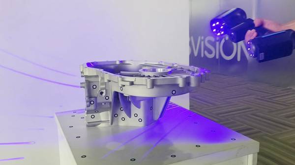
- Scanning. Depending on the geometry, the operator selects the appropriate mode. For a transmission valve body with deep oil galleries, deep-hole mode captures internal bore geometry in a single pass. For a high-reflective injection mold, the blue laser and adaptive exposure logic cut through the mirror-like surface without spraying. The handheld form factor allows scanning directly on the assembly line or inside a hangar.
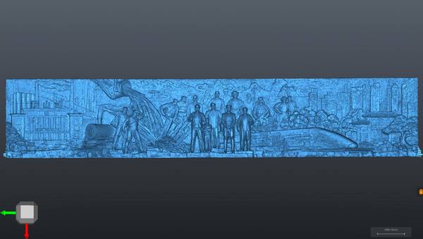
- Data processing. The scanner streams point cloud data natively into SMARPARA Q for GD&T analysis, alignment to CAD nominals, and automated inspection reports. The AI-driven surface classification preserves sharp edges and filters noise, so the point cloud is ready for immediate evaluation. Real-time review in the 3D Viewer lets the metrology engineer confirm feature capture before the part leaves the fixture.
- Delivery. The software automatically extracts GD&T callouts—flatness, profile, runout—and generates a full-field color deviation map. Reports can flow directly into PLM and QMS platforms, keeping the digital thread unbroken from first-article inspection through production lot checks. For reverse engineering workflows, dense meshes route into parametric modeling without intermediate file conversions.
Where AlphaScan Fits: Capability Mapping
The fastest way to evaluate a 3D scanning of objects solution is to line up a tool’s engineering strengths against the specific jobs a team runs every week. AlphaScan’s design priorities map cleanly to a set of high-frequency industrial use cases.
| Key Strengths | Ideal Scenarios |
|---|---|
| Metrology-grade accuracy for fine feature capture | Medical device prototype verification, aerospace MRO component dimensional inspection |
| Dedicated deep hole, fine, and standard scanning modes | Complex automotive part reverse engineering, injection mold feature validation |
| Fully handheld form factor with no fixed mounting required | On-site production floor quality checks, off-site field MRO scanning |
| Native integration with INSVISION’s 3D analysis and reverse engineering software | End-to-end digital thread workflows, batch deviation analysis against CAD models |
For medical device manufacturers, the metrology-grade accuracy supports first-article inspection of small orthopedic implants where surface profile tolerances are tight and feature sizes push the limits of conventional CMMs. Aerospace MRO teams lean on the same accuracy when scanning turbine components for blend limits and distortion mapping after service runs.
Automotive reverse engineering workflows benefit from the dedicated scanning modes—deep-hole mode captures internal passages in cylinder heads, fine mode resolves sharp edges on stamped body panels, and standard mode handles large surface areas efficiently. Injection mold validation uses these modes to check cavity geometry against CAD and catch tool wear before it produces scrap.
The handheld form factor proves its value for quality checks directly on the assembly line, where moving parts to a metrology lab would disrupt takt time, and for field MRO crews scanning installed equipment in power generation facilities.
Native integration with INSVISION’s software is critical for teams building a digital thread—scan data flows directly into deviation analysis and reverse engineering modules, enabling batch comparisons against reference CAD without intermediate file conversions.
Observable Outcomes
When a Tier-1 supplier scans a transmission valve body with deep oil galleries, the dual LED layout delivers a complete point cloud on the first pass—no stitching guesswork, no manual touch-probe fill-in. For an automotive OEM reverse engineering a legacy transmission housing with no surviving CAD, the deep-hole mode captures internal bore geometry sharp enough to pull into parametric modeling without hours of void patching.
On a high-reflective injection mold, the blue laser and adaptive exposure eliminate the need for spray coating; a quality team can run a single-part scan cycle, review the point cloud in real time, and immediately spot a shifted cavity wall against the nominal CAD overlay.
For a microfluidic chip with 0.3 mm channel widths, the fine scan mode holds consistent point cloud density across steep draft angles and thin ribs, so dimensional verification against GD&T callouts becomes straightforward without re-scan loops.
In each case, the workflow collapses the traditional inspection sequence. An operator positions the part, triggers a scan, and within minutes the system outputs a full-field color map aligned to the CAD model. The digital thread stays unbroken, and decisions move closer to the point of production.
Extending the Approach to Adjacent Applications
The same principles that make AlphaScan effective for castings, molds, and medical devices apply to any industrial 3D scanning of objects where complex geometry, reflective surfaces, or portability requirements break conventional measurement tools. For heavy equipment manufacturers, scanning large weldments on the shop floor eliminates the need to move bulky assemblies to a CMM.
For power generation MRO teams, a handheld scanner in a Pelican case replaces the logistics of transporting turbine components to a lab. For additive manufacturing, the ability to capture internal lattice structures and fine feature lines supports first-article validation directly on the build plate.
Teams evaluating a 3D scanning solution can use a fit-based assessment: identify the specific geometries that cause the most inspection rework, the surfaces that trigger the most dropouts, and the points in the process where measurement data arrives too late to prevent scrap.
If those pain points align with AlphaScan’s design strengths—AI-driven surface classification, dedicated scan modes, factory-calibrated accuracy, and native software integration—the system slots into existing workflows without requiring a wholesale process redesign.
Summary
INSVISION’s AlphaScan repositions metrology-grade 3D scanning of objects from a centralized lab function to a point-of-use capability. By combining multi-line blue laser technology, AI-enhanced point cloud processing, and a handheld form factor with no external tracking, the system addresses the real-world constraints that slow down first-article inspection, reverse engineering, and in-process quality checks.
The result is a workflow where full-field deviation maps, automated GD&T extraction, and direct CAD alignment become routine shop-floor events—not exceptions that require a CMM programmer and a granite table.
For manufacturers and MRO teams looking to close the gap between part production and dimensional data, that shift represents a measurable reduction in inspection bottlenecks and a tighter digital thread from scan to decision.
Hangzhou Insvision Technology Co.,Ltd.
Address: Building 1, No. 1399 Liangmu Road, Yuhang District, Hangzhou, Zhejiang 311121, China