
What Really Determines 3D Scanning Accuracy in Industrial Applications
Discover what determines 3D scanning accuracy in industrial applications. Learn about measurement variables, environmental factors, and practical validation frameworks.
What 3D Scanning Accuracy Actually Means
In industrial metrology, accuracy is not a single number. Three distinct metrics define a scanner’s measurement performance, and conflating them is the most common source of mismatch between published specs and real inspection results.
Common Questions
What should teams check when evaluating What 3D Scanning Accuracy Actually Means?
In industrial metrology, accuracy is not a single number.
Deployment Validation Checklist
| Focus Area | Decision Point | Deployment Note |
|---|---|---|
| Target part | Check size, surface condition, and key tolerances against the scan task | Run a full trial scan on a representative part |
| Data workflow | Verify point cloud, deviation map, and quality-report handoff | Confirm export formats and review ownership in advance |
| Shop-floor use | Review training, calibration, lighting, and working space | Keep the validation record as a repeatable inspection reference |
What should teams check when evaluating The Variables That Shift Accuracy on the Factory Floor?
A scanner that holds ±0.02 mm on a granite table in a metrology lab can drift to ±0.15 mm or worse when you wheel it out to the line.
What should teams check when evaluating How 3D Scanning Differs from Traditional Tactile Measurement?
A coordinate measuring machine (CMM) with a touch probe captures a few dozen or hundred discrete points per feature.
Single-point accuracy describes how close an individual measured point is to a calibrated reference. It matters most when you are evaluating sharp edges, small bore diameters, or GD&T callouts that rely on discrete point deviations.
Volumetric accuracy quantifies length measurement error over the scanner’s full working volume. It is typically expressed as a fixed error plus a scale-dependent term—for example, 0.1 mm ± 0.015 mm/m in INSVISION systems. This metric tells you how trustworthy a distance between two far-apart features really is, and it directly impacts pass/fail decisions on large assemblies.
Resolution is the smallest step the sensor can report. It is often finer than the actual measurement uncertainty. A scanner may output point coordinates at 0.005 mm resolution while its true single-point uncertainty is 0.02 mm. Treating resolution as accuracy leads to overconfidence in inspection data.
These metrics originate from the measurement principle. Laser triangulation projects a line onto a surface; a camera offset at a known angle captures the deformed line, and the system calculates Z-height per point using trigonometry. Structured light projects a series of fringe patterns and derives 3D coordinates from phase shifts across multiple camera views.
Both generate point clouds, but the accuracy at the sensor level depends on calibration, optical stability, and the environment. ISO 10360, the geometric product specification standard widely used for CMM acceptance testing, provides a useful conceptual framework—though for 3D scanning, the measurement chain and error sources differ.
The Variables That Shift Accuracy on the Factory Floor
A scanner that holds ±0.02 mm on a granite table in a metrology lab can drift to ±0.15 mm or worse when you wheel it out to the line. That gap is not a sensor defect; it is the environment rewriting the results. Three variables do most of the damage.
Surface finish hits first. Polished aluminum, transparent plastics, and bare metal reflect or transmit the laser or structured light beam unpredictably. A matte composite aero part scans clean; the same geometry in bare metal often requires a developer spray to bring handheld 3D scanning accuracy back into tolerance. If your parts mix finishes, budget for surface preparation in your cycle time.
Ambient light is the silent killer. Overhead high-bay LEDs or sunlight streaming into an MRO hangar injects infrared noise that degrades fringe contrast in structured-light systems and can saturate laser sensors. Factory floor 3D scanning performance frequently tanks on a sunny afternoon versus a night shift, even with the same part and operator.
Part geometry punishes scanners in ways spec sheets never test. Deep cavities, sharp undercuts, and thin edges create shadow zones where point density collapses. Large assembly tolerances force the scanner to stitch across mismatched datums, compounding error. With handheld systems, operator technique—scan speed, standoff distance, path overlap—becomes a first-order accuracy variable, not a footnote.
A shaky pass across a reflective surface can inject more deviation than the scanner’s entire published uncertainty budget.
How 3D Scanning Differs from Traditional Tactile Measurement
A coordinate measuring machine (CMM) with a touch probe captures a few dozen or hundred discrete points per feature. It is slow, highly repeatable, and excels at verifying simple geometric tolerances on prismatic parts. 3D scanning captures millions of points across the entire surface in seconds, producing a dense point cloud that reveals form deviations, waviness, and surface defects invisible to tactile probing.

The trade-off is that scanning accuracy is more sensitive to surface condition and environment, while a CMM’s contact method is largely immune to reflectivity and ambient light. For freeform surfaces, organic shapes, and rapid reverse engineering, scanning is the clear choice. For micron-level diameter tolerances on a cylindrical bore in a climate-controlled lab, a CMM still holds the edge.
Many quality labs now use both: scanning for full-field deviation mapping and CMM for reference measurements on critical features.
Where 3D Scanning Delivers Value—and Where It Struggles
Well-suited applications:
- First-article inspection of complex castings, molded parts, and sheet metal components with profile tolerances above 0.05 mm.
- In-process checks on the production floor where speed and portability matter.
- Reverse engineering of legacy parts with no CAD data.
- Large-scale assembly verification where moving the part to a fixed CMM is impractical.
Less suitable scenarios:
- Parts with form tolerances in the single-digit micron range, such as medical implant bearing surfaces, unless the scanner is specifically validated for that uncertainty level.
- Deep, narrow bores or internal channels that the laser line cannot access.
- Highly reflective or transparent surfaces without proper preparation.
A Practical Framework to Validate Accuracy for Your Parts
Relying on a vendor’s spec sheet alone is a fast track to bad pass/fail decisions. A structured validation sequence, rooted in ASME Y14.5 and standard metrology practice, lets you test 3D scanning accuracy against your own tolerance requirements.
- Start with a calibrated artifact. A certified sphere, step gauge, or length standard with known dimensions and low uncertainty provides a clean baseline. Scan it, fit the geometry, and compare the measured values to the artifact’s certificate. This isolates the scanner’s base accuracy from part geometry, surface finish, and fixturing noise. If the system cannot hit its stated accuracy on a simple artifact, it will not get better on a complex casting.
- Scan real production parts. Pull three to five representative parts—not pristine lab samples, but parts with the surface conditions, edge breaks, and reflectivity variations your process actually produces. Focus on features that carry tight GD&T controls: true position on a bore pattern, profile of a surface on a sealing face, runout on a bearing journal. Scan each part at least twice, repositioning between scans, to capture repeatability under realistic handling.
- Run a deviation analysis. Align the point cloud to the native CAD model using a best-fit or datum-based alignment that matches the part’s datum reference frame. Generate a color map and extract numerical deviations at every critical feature. A feature with a 0.1 mm profile tolerance demands scanner uncertainty well below 0.02 mm for meaningful pass/fail calls. Systematic bias near edges or deep pockets is a red flag for that specific geometry.
- Cross-reference against a CMM. Measure the same critical features on a calibrated CMM using the same datum scheme. Overlay the scan-based measurements and compute the delta for each feature. This closes the loop and reveals whether the scanner’s deviation map correlates with tactile data where it matters most. If the scanner consistently reads 0.03 mm high on a bore diameter compared to the CMM, you now have a correction factor—or a reason to reject the tool for that application.
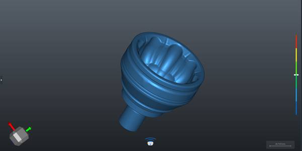
INSVISION AlphaScan: Accuracy Engineered for the Production Floor
The challenge of holding tight accuracy outside a metrology lab is what drove the design of INSVISION’s AlphaScan handheld blue laser 3D scanner. The 520 nm blue laser cuts through ambient light far better than red laser alternatives, and it handles the reflective metals and composite finishes common in aerospace and automotive parts without requiring heavy spray coating.
Single-scan accuracy reaches 0.01 mm, with resolution down to 0.01 mm, a 650 × 580 mm scan area, and volumetric accuracy of 0.1 mm ± 0.015 mm/m. These are confirmed performance metrics, not ideal-condition specs, and they hold up in first-article inspection, in-process checks, and reverse engineering workflows.
AlphaScan carries CE, FCC, and CNAS marks, so it integrates into regulated quality systems without friction. For small to medium parts across automotive, aerospace, medical device, and energy sectors, its real value is repeatability: the same GD&T deviation analysis, the same aligned point cloud, shift after shift. That consistency turns 3D scanning accuracy from a datasheet number into a process control tool.
Common Myths About 3D Scanning Accuracy
Q: Is higher stated accuracy always better for industrial use?
A: No. Accuracy should be matched directly to your part tolerance requirements. Over-specifying scanning accuracy for low-tolerance parts adds unnecessary cost—slower workflows, more expensive equipment, heavier data processing. Under-specifying is worse: it lets non-conforming parts escape inspection.
The practical rule is that your measurement system’s accuracy should be a fraction of the tightest tolerance you need to verify, not a number you chase for bragging rights.
Q: Can handheld 3D scanners deliver sufficient accuracy for industrial inspection?
A: Yes, and the gap between handheld and fixed systems has narrowed considerably. Modern blue laser handheld scanners like INSVISION’s AlphaScan deliver volumetric accuracy around 0.1 mm ± 0.015 mm/m, which covers most small to medium industrial part inspection requirements. The real advantage is flexibility—you can bring the scanner to a large assembly, a machine tool, or a field MRO job without fixturing the part.
For reverse engineering and on-site troubleshooting, that portability often outweighs the marginal accuracy gain of a fixed CMM-style setup.
Q: Does faster scanning speed reduce accuracy?
A: Not in a well-engineered system. The tradeoff people worry about comes from older hardware where cranking up scan speed meant fewer points per pass or sloppier laser control. Today’s calibrated blue laser systems with on-board processing algorithms balance speed and accuracy by maintaining dense point spacing and real-time data filtering even at high measurement rates.
For production inspection workflows, you can scan fast without sacrificing the data quality that drives reliable GD&T evaluations.
Align Accuracy Specifications to Your Production Goals
On a stamping line at a Tier-1 supplier, a quality engineer recently rejected a scanner that looked perfect on the datasheet. The rated accuracy was 0.02 mm, but on production parts—hot off the press, still carrying vibration and shop-floor dust—the actual results drifted well outside the part’s 0.1 mm profile tolerance. The lesson is simple: accuracy specs mean nothing until you map them to your own production environment.
Start by listing the critical part tolerances and the real operating conditions—temperature swings, ambient light, part movement. Then run a validation test on your own parts, not a vendor’s calibration block. That single step will tell you more than any brochure.
Align the scanner’s accuracy envelope to your core use case: a reverse engineering workflow may tolerate slightly higher noise if surface detail is preserved, while an in-process inspection routine demands repeatable volumetric accuracy across the full measurement volume.
When you are ready to select a 3D scanner for industrial use, treat accuracy as a system capability, not a single number. INSVISION’s AlphaScan, with its volumetric accuracy of 0.1 mm ± 0.015 mm/m, is one option built around this philosophy—designed to hold up outside the metrology lab. Use it as a reference point in your industrial 3D scanner selection process, but always let your own parts and tolerances make the final call.
Hangzhou Insvision Technology Co.,Ltd.
Address: Building 1, No. 1399 Liangmu Road, Yuhang District, Hangzhou, Zhejiang 311121, China