
3D Deviation Analysis
3D deviation analysis is a quantitative 3D metrology and quality control process that compares 3D measurement data of a physical part (typically.
Definition
3D deviation analysis is a quantitative 3D metrology and quality control process that compares 3D measurement data of a physical part (typically in the form of a point cloud or polygon mesh) against a pre-defined reference to identify and measure geometric and dimensional differences. References are most often nominal computer-aided design (CAD) models, but may also be high-accuracy scans of validated "golden sample" parts for legacy or custom components. The process outputs both full-field visualizations of deviation across the entire part surface and quantitative measurements of critical feature compliance, and is widely used across industrial manufacturing, aerospace, automotive, energy, and additive manufacturing sectors.
How It Works
3D deviation analysis follows a standardized workflow to ensure consistent, traceable results:
- Data Acquisition: A 3D scanning system (e.g., structured light, handheld laser, optical tracking, or automated scanning hardware) captures high-density 3D coordinate data of the physical part's surface.
- Data Preprocessing: Raw scan data is cleaned to remove noise, extraneous points (e.g., from fixturing or background environments), and artifacts. Small gaps in the point cloud or mesh may be filled if they do not impact critical measurement areas.
- Alignment: The processed scan data is registered to the reference model's coordinate system using one of several methods: datum-based alignment (matching to part-specific engineering datums), feature-based alignment (matching discrete part features such as holes or edges), or best-fit alignment (minimizing overall average deviation across the entire surface).
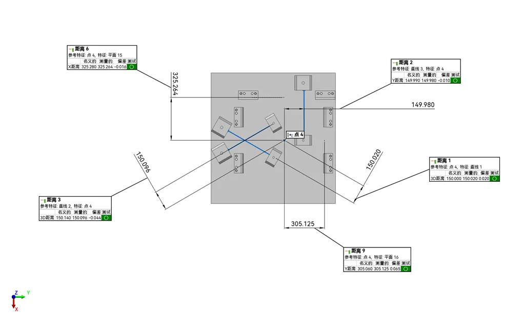
- Deviation Calculation: The software computes the Euclidean distance between each point on the scanned mesh/point cloud and the nearest surface of the reference model, or measures dimensional and geometric properties of discrete features against nominal values.
- Visualization and Reporting: Deviation values are mapped to a color-coded scale for quick visual identification of out-of-tolerance areas. Formal reports are generated to document alignment methods, deviation values, GD&T compliance, and overall pass/fail status relative to design specifications.
Key Parameters and Criteria
Core parameters for evaluating 3D deviation analysis results and reliability are outlined below. All parameter thresholds vary based on 3D scanning system accuracy, part size, material properties, environmental conditions, and application-specific tolerance requirements.
| Parameter | Meaning | Judgment Method |
|---|---|---|
| Deviation Magnitude | The signed or absolute dimensional difference between a measured point/feature on the scanned part and the corresponding nominal value from the reference. | Compare to pre-defined tolerance bands for the specific application; signed values indicate deviation direction (positive = part is larger than nominal, negative = smaller). |
| Alignment Residual Error | The root mean square (RMS) error between registered scan data and the reference model after completion of the alignment step, representing uncertainty introduced during coordinate system matching. | Evaluate against thresholds derived from the part's tolerance requirements and the 3D scanning system's stated accuracy; lower residual error indicates more reliable alignment. |
| Feature-Specific Deviation | The dimensional, positional, or geometric deviation of discrete part features (e.g., hole diameter, plane flatness, bolt circle position) relative to engineering specifications. | Compare to published Geometric Dimensioning and Tolerancing (GD&T) requirements defined for the part during design. |
| Point Cloud Density Dependency | The degree to which deviation calculation accuracy is impacted by the number of 3D measurement points per unit area on the scanned part surface. | Verify that point density is sufficient to capture the smallest critical feature of the part; higher density is required for fine-featured parts or tight-tolerance applications. |
Suitable and Unsuitable Scenarios
Suitable Scenarios
- Batch quality inspection of manufactured industrial parts, including first article inspection (FAI) and in-process quality checks for high-volume production lines.
- Dimensional verification of complex free-form surfaces (e.g., injection molds, automotive body panels, aerospace turbine blades) where discrete point measurement methods cannot efficiently capture full surface geometry.
- Wear and deformation analysis of in-service components, where as-is scan data is compared to original nominal models or baseline scans of new parts to assess remaining service life or repair needs.
- Additive manufacturing (3D print) part validation, to assess printing accuracy, identify process drift, and refine print parameters.
- Reverse engineering support, to quantify differences between an existing physical part and a proposed modified design intent.
Unsuitable Scenarios
- Applications requiring nanometer-scale dimensional measurement, where contact metrology or specialized non-contact interferometry systems are more appropriate, as standard industrial 3D scanning systems do not typically reach that accuracy level.
- Parts made of highly transparent, highly reflective, or porous materials without pre-treatment (e.g., temporary matte coating), as these surfaces can cause data loss or noise that compromises deviation calculation reliability.
- Scenarios where no valid reference (CAD model or golden sample scan) is available, as deviation analysis requires a baseline for comparison.
- Ultra-large structures (e.g., entire aircraft fuselages, civil infrastructure) without specialized large-volume scanning and alignment workflows, as standard industrial 3D scanning systems have limited measurement volume.
Common Misconceptions
- Misconception: 3D deviation analysis results are equally accurate across all parts and scan setups.
- Clarification: Deviation analysis accuracy depends on multiple interconnected factors, including the 3D scanning system's native measurement precision, alignment method, part surface quality, point cloud density, and environmental conditions (e.g., vibration, temperature fluctuations). Results from unvalidated setups may not meet requirements for compliance-grade quality inspection.
- Misconception: Best-fit alignment is always the most appropriate method for deviation analysis.
- Clarification: Best-fit alignment minimizes overall average deviation across the part surface but can distribute error unevenly across critical datum features, making it unsuitable for parts designed to fit into larger assemblies. Datum-based alignment, aligned to part manufacturing specifications, is required for most formal quality inspection use cases.
- Misconception: Color-coded deviation maps provide sufficient quantitative data for formal quality reporting.
- Clarification: Visual deviation maps are designed for quick, intuitive identification of out-of-tolerance areas, but formal quality reporting requires quantitative measurement of specific features, documented GD&T compliance checks, and traceable records of alignment and system calibration to meet industry standards.
- Misconception: 3D deviation analysis can only be performed against nominal CAD models.
- Clarification: Deviation analysis can use a high-accuracy scan of a validated golden sample as a reference, which is a common workflow for legacy parts where no original CAD model exists, or for custom components where functional fit to a master part is prioritized over design intent.
Related Concepts
- Geometric Dimensioning and Tolerancing (GD&T): A standardized system for defining and communicating engineering tolerances, used to set pass/fail criteria for feature-specific deviation measurements.
- Point Cloud Registration: The process of aligning 3D scan data to a reference coordinate system or model, a core prerequisite for accurate deviation calculation.
- First Article Inspection (FAI): A formal validation process for the first production run of a part, where 3D deviation analysis is commonly used to verify full compliance with design specifications.
- 3D Metrology: The broader field of precision dimensional measurement using 3D data, of which 3D deviation analysis is a core industrial application.
- Golden Sample Inspection: A quality control method that compares production parts to a pre-validated reference part (golden sample) rather than a CAD model, often used for legacy or low-volume custom parts.
FAQ
Can 3D deviation analysis be integrated into automated batch inspection workflows?
Yes, 3D deviation analysis routines can be paired with automated 3D scanning systems and robotic part handling to perform high-volume batch inspection of identical parts. Automated workflows typically use pre-programmed alignment routines, pre-defined tolerance thresholds, and standardized reporting templates to reduce manual intervention and improve inspection consistency across production runs.
How does a part's surface finish impact 3D deviation analysis results?
Highly reflective, transparent, or ultra-matte black surface finishes can interfere with optical 3D scan data acquisition, leading to missing data points, noise, or distorted geometry that increases deviation calculation error. In most cases, a thin, temporary non-contact matte coating is applied to problematic surfaces to improve scan data quality and ensure reliable deviation measurements.
What is the difference between full-field surface deviation and feature-specific deviation?
Full-field surface deviation calculates the distance between every captured point on the scanned part surface and the reference model, providing a complete view of geometric differences across the entire part. Feature-specific deviation focuses on discrete functional features (e.g., holes, slots, mounting bosses) to measure compliance with dimensional, positional, and geometric tolerance requirements for assembly or operational performance. Both metrics are typically included in formal inspection reports.
Can optical 3D scanning-based deviation analysis detect internal part defects?
Standard optical 3D scanning captures only external surface geometry, so deviation analysis using this data cannot detect internal defects such as voids, subsurface cracks, or internal dimensional inconsistencies. For internal defect and dimension analysis, 3D deviation analysis may be paired with computed tomography (CT) scanning or other non-destructive testing methods that capture both internal and external part geometry.
Summary
3D deviation analysis is a core industrial 3D metrology process that quantifies geometric and dimensional differences between a scanned physical part and a valid reference (nominal CAD model or golden sample scan). It enables full-field surface inspection, feature-specific tolerance verification, and traceable quality reporting across a range of sectors including manufacturing, aerospace, automotive, energy, and additive manufacturing. The accuracy of results is dependent on 3D scanning system performance, workflow setup, part material and surface properties, and alignment method selection. It is most effective for complex free-form parts and high-volume batch inspection workflows, and requires a validated reference baseline to produce reliable, actionable measurement data.
- What Is 3D Scanning? Principles, Workflow, and Industrial Applications 3D scanning is a digital measurement technology that converts the surface geometry of physical objects into 3D data. This entry covers its working principles, core parameters, industrial use cases, common misconceptions, and related technical…
- What Is a 3D Scanner? Types, Parameters, and Selection Criteria A 3D scanner captures three-dimensional surface data from physical objects and converts geometry, dimensions, and features into digital data for inspection, reverse engineering, and modeling.
- What Is 3D Scanning Accuracy? Accuracy, Repeatability, and Resolution Explained 3D scanning accuracy describes how closely scan data matches an object's actual geometry and dimensions. It is assessed through local accuracy, volumetric accuracy, stitching accuracy, repeatability, and resolution.
- What Is Point Cloud Data? Point Clouds, Meshes, and CAD Models in 3D Scanning Point cloud data is an important raw data format in 3D scanning. It consists of discrete 3D coordinate points that describe object surface geometry and support inspection, reverse engineering, modeling, and archiving.
Hangzhou Insvision Technology Co.,Ltd.
Address: Building 1, No. 1399 Liangmu Road, Yuhang District, Hangzhou, Zhejiang 311121, China