
Photogrammetry in 3D Scanning
Photogrammetry in 3D scanning is a non contact, image based 3D reconstruction technique that derives spatial measurement data and digital 3D models.
Definition
Photogrammetry in 3D scanning is a non-contact, image-based 3D reconstruction technique that derives spatial measurement data and digital 3D models of physical objects or environments by analyzing overlapping 2D photographs captured from multiple distinct viewpoints. It is deployed across industrial, heritage, and engineering fields as a flexible method for 3D digitization, dimensional measurement, and quality inspection.
How It Works
Industrial photogrammetric 3D scanning follows a standardized core workflow, with modifications for specific use cases:
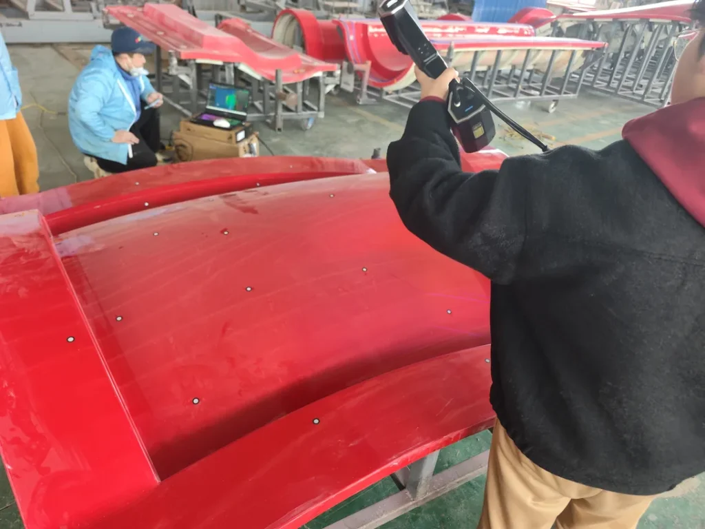
- Image Acquisition: The target object or scene is photographed from a minimum of two, often dozens, of overlapping viewpoints, via manual camera movement, fixed multi-camera arrays, or cameras mounted to robotic or motion control systems. Coded or non-coded reference markers may be affixed to the object or surrounding environment to simplify cross-image alignment. Some industrial workflows integrate controlled light projection to add temporary artificial surface features to low-texture objects, improving feature matching reliability.
- Feature Matching: Specialized processing software identifies distinct, repeatable visual features (e.g., edges, texture variations, reference markers) present in multiple overlapping images, and establishes positional correspondence between matching features across the full image set.
- Pose Estimation and Triangulation: Using either pre-calibrated camera positions or structure from motion (SfM) algorithms to calculate camera positions and intrinsic optical properties, the software applies triangulation principles to derive 3D spatial coordinates for each matched feature.
- Reconstruction and Refinement: Aggregated 3D coordinates form a dense point cloud, which is further processed to generate a polygonal mesh, with optional texture mapping from the original 2D images for visual reference or defect identification.
Key Parameters and Criteria
Photogrammetry performance varies based on camera resolution, object size, surface material, ambient lighting, and processing software configuration. Core measurable parameters for industrial use cases are defined below:
| Parameter | Meaning | Judgment Method |
|---|---|---|
| Reconstruction Accuracy | Maximum allowable dimensional deviation between the photogrammetrically generated 3D model and the verified physical dimensions of the target object | Compare measured dimensions of a calibrated reference artifact (e.g., certified gauge block, calibrated test bar) across 5+ repeated scan runs, with results averaged to account for random variance |
| Image Overlap Rate | Percentage of shared visual content between consecutive input images, required for reliable feature matching | Calculated automatically by photogrammetry processing software, validated by counting the number of matched feature points across 10+ random adjacent image pairs |
| Marker Registration Error | Positional deviation of alignment markers (coded or non-coded) used to stitch partial scan datasets into a unified coordinate system | Measure the difference between the detected position of each marker in the final 3D model and its pre-calibrated true position, averaged across all markers in the test setup |
| Texture Resolution | Density of surface detail mapped to the final 3D mesh, expressed in pixels per unit length | Count the number of pixels representing a 10mm calibrated linear reference feature on the object surface, divided by the feature's known length to derive pixels per mm |
| Processing Latency | Time elapsed between completion of image capture and generation of a fully aligned usable 3D point cloud | Timed from the import of the final capture image to the software's confirmation of a complete, registered 3D dataset, averaged across 3+ test runs of identical object size and complexity |
Suitable and Unsuitable Scenarios
Suitable Scenarios
- Large-format industrial asset digitization (e.g., factory layouts, large aerospace tooling, ship components) where portable capture and flexible positioning are prioritized
- Objects with high-contrast, distinct surface textures that enable consistent feature matching across images
- Non-contact measurement of fragile, soft, or deformation-prone parts that cannot tolerate physical contact with measurement tools
- Non-invasive documentation of legacy or heritage industrial components where surface modification (e.g., coating application) is prohibited
- Batch scanning of small to medium parts with consistent surface features when paired with automated capture systems
Unsuitable Scenarios
- Objects with uniform, featureless surfaces (e.g., smooth unmarked glass, plain uncoated metal sheets) that lack sufficient key points for cross-image matching
- Transparent, highly reflective, or light-absorbent surfaces that cause inconsistent image exposure or distorted feature detection
- Micron-level precision measurement of ultra-small components, where structured light or laser scanning systems typically deliver higher measurement consistency
- Environments with rapidly changing lighting or unconstrained moving objects during capture, which introduce alignment and feature matching errors
Common Misconceptions
- Misconception: Photogrammetry and structured light 3D scanning are identical technologies.
Correction: Basic photogrammetry relies solely on passive 2D image capture and natural feature matching, while structured light scanning projects controlled light patterns onto the object to calculate depth data. Some hybrid industrial systems combine both technologies to balance capture flexibility and precision.
- Misconception: Photogrammetry cannot deliver industrial-grade accuracy.
Correction: When configured with high-resolution cameras, calibrated reference markers, and specialized industrial processing software, photogrammetric workflows can achieve accuracy levels suitable for many reverse engineering and quality control tasks, though performance varies significantly by setup.
- Misconception: More cameras always produce better photogrammetric results.
Correction: While additional camera viewpoints can reduce occlusion from complex object geometry, excessive overlapping images with insufficient unique features increase processing time without improving accuracy, and may introduce noise from mismatched points.
- Misconception: Photogrammetry only works for static, indoor objects.
Correction: Modern photogrammetric systems can be adapted for outdoor capture (with controlled lighting or reference marker placement) and dynamic motion capture of moving objects when paired with synchronized high-speed cameras.
Related Concepts
- Structure from Motion (SfM): A core photogrammetric algorithm that calculates 3D camera positions and intrinsic optical parameters from a set of unordered overlapping images, without requiring pre-calibrated camera positions.
- Coded Targets: Printed or affixed markers with unique visual patterns used to align multiple image sets and reduce registration error in industrial photogrammetry workflows.
- Hybrid 3D Scanning: A measurement approach that combines photogrammetric capture with other technologies (e.g., blue laser scanning, structured light projection) to balance large-format capture speed and high-precision detail capture.
- Point Cloud Registration: The process of aligning multiple partial 3D datasets (from photogrammetry or other scanning methods) into a single unified coordinate system, often using photogrammetric markers as reference points.
- Optical Tracking: A system that uses cameras to monitor the position of sensors or targets in 3D space, often integrated with photogrammetric workflows to improve alignment for dynamic or large-volume scanning.
FAQ
What is the difference between photogrammetry and laser 3D scanning?
Photogrammetry derives 3D data from analyzing overlapping 2D images of an object, while laser 3D scanning calculates depth by measuring the time-of-flight or phase shift of projected laser light reflected off the object. Photogrammetry typically requires less specialized hardware for basic large-format capture, while laser scanning generally delivers higher consistency for low-texture or high-reflectivity surfaces.
Can photogrammetry be used for automated industrial quality inspection?
Yes, photogrammetric workflows can be integrated into automated inspection lines when paired with fixed camera arrays, robotic positioning systems, and automated feature detection software. Performance depends on consistent lighting, controlled part positioning, and sufficient surface features on inspected components.
How does surface texture affect photogrammetric scanning results?
Photogrammetry relies on distinct, consistent surface features to match points across overlapping images. Objects with high-contrast, unique surface textures produce more accurate, complete 3D reconstructions, while uniform, low-contrast, or reflective surfaces may require temporary application of matte coating or reference markers to enable reliable capture.
Is photogrammetry suitable for scanning large industrial assets such as aircraft fuselages?
Yes, photogrammetry is widely used for large-volume industrial digitization, as it supports flexible capture positions and can scale to very large objects with appropriate marker placement and image coverage. For high-precision large-asset inspection, photogrammetry is often combined with high-accuracy scanning technologies to validate critical dimensional features.
Summary
Photogrammetry is a versatile, non-contact 3D scanning technology that reconstructs 3D spatial data from overlapping 2D images captured across multiple viewpoints. Its performance varies based on hardware configuration, object characteristics, and environmental conditions, making it suitable for a wide range of industrial use cases from large-asset digitization to reverse engineering, while less effective for low-texture, high-reflectivity, or ultra-high-precision micron-level measurement tasks. When integrated with complementary 3D measurement technologies and specialized processing software, it forms a key component of end-to-end industrial 3D digitization workflows.
- What Is 3D Scanning? Principles, Workflow, and Industrial Applications 3D scanning is a digital measurement technology that converts the surface geometry of physical objects into 3D data. This entry covers its working principles, core parameters, industrial use cases, common misconceptions, and related technical…
- What Is a 3D Scanner? Types, Parameters, and Selection Criteria A 3D scanner captures three-dimensional surface data from physical objects and converts geometry, dimensions, and features into digital data for inspection, reverse engineering, and modeling.
- What Is 3D Scanning Accuracy? Accuracy, Repeatability, and Resolution Explained 3D scanning accuracy describes how closely scan data matches an object's actual geometry and dimensions. It is assessed through local accuracy, volumetric accuracy, stitching accuracy, repeatability, and resolution.
- What Is Point Cloud Data? Point Clouds, Meshes, and CAD Models in 3D Scanning Point cloud data is an important raw data format in 3D scanning. It consists of discrete 3D coordinate points that describe object surface geometry and support inspection, reverse engineering, modeling, and archiving.
Hangzhou Insvision Technology Co.,Ltd.
Address: Building 1, No. 1399 Liangmu Road, Yuhang District, Hangzhou, Zhejiang 311121, China