
Scan to CAD Explained Delivering Production Ready Models with Handheld 3D Scanning
Learn how scan to CAD workflows bridge the gap between physical parts and parametric models. Discover how handheld 3D scanning delivers production-ready CAD data.
What Scan to CAD Actually Means
Scan to CAD is the process of capturing the geometry of a physical object and converting that data into a feature-based CAD model that can be edited, simulated, and manufactured against. The input is typically a point cloud or polygon mesh.
The output is a parametric solid or surface model — complete with sketches, extrusions, fillets, and hole features — that behaves natively inside software such as SolidWorks, CATIA, NX, or Inventor.
The workflow sits at the intersection of metrology, reverse engineering, and design. It is not simply “3D scanning plus file conversion.” The critical step is the translation from unstructured scan data to structured CAD geometry. That translation can follow several paths:
- Mesh-to-surface fitting: The scan mesh is used as a reference to manually or semi-automatically build NURBS surfaces.
- Feature extraction: Algorithms identify planes, cylinders, cones, and other primitives and reconstruct them as parametric features.
- Hybrid modeling: A combination of automatic feature recognition and manual surfacing, often used for parts with both prismatic and organic shapes.
- Direct mesh import with history: Some CAD packages now accept mesh bodies and allow limited feature creation on top, but this is not a true parametric model.
The choice of path depends on the part geometry, the intended use of the CAD model, and the tolerance requirements of downstream processes like CNC machining, FEA, or first-article inspection.
Key Technical Elements That Determine Scan-to-CAD Success
A scan-to-CAD pipeline is only as strong as its weakest link. Three elements consistently separate production-grade workflows from lab exercises.
Data quality at the point of capture. The scanner must deliver low-noise, high-resolution data across the surfaces that matter. For prismatic parts, sharp edges and flat faces are non-negotiable. For organic shapes, smooth curvature transitions are essential. Handheld scanners that rely on marker alignment or feature tracking must maintain volumetric accuracy across the entire part, not just in a localized region.
Format fidelity and interoperability. The raw output — usually an STL, OBJ, or PLY mesh — is just the starting point. What matters is how cleanly that mesh moves into reverse engineering software (Geomagic Design X, Quicksurface, Mesh2Surface) and then into the target CAD system. Any decimation, re-meshing, or coordinate system mismatch introduces error that compounds with each handoff.
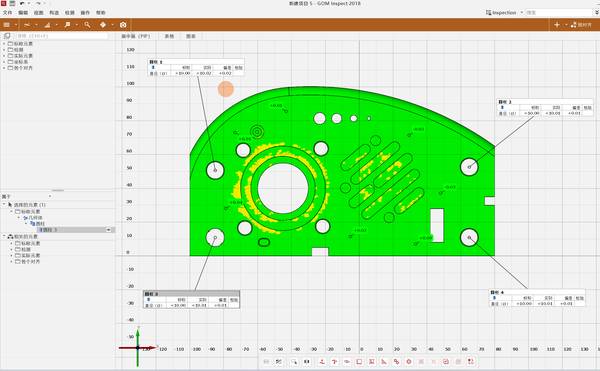
Metrology traceability. In many industrial applications, the scan-to-CAD model must be verifiable against GD&T callouts. This means the scanner’s accuracy statements need to be backed by measurement on certified artifacts, and the resulting CAD model should overlay with a deviation map that an inspection team can trust. Without this, the model is a visual reference at best.
How AlphaScan Addresses Scan-to-CAD Data Quality
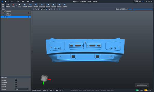
INSVISION’s AlphaScan handheld 3D scanner is engineered to feed the scan-to-CAD pipeline with metrology-grade data from the first step. It uses blue laser technology to capture fine surface detail with minimal noise, even on reflective or dark surfaces that typically require spray coating.
The scanner’s high point density and edge-preserving algorithms help maintain the crisp boundaries that feature extraction software relies on.
Rather than treating scan-to-CAD as an afterthought, the AlphaScan system outputs structured data that aligns with the expectations of reverse engineering software. The mesh resolution can be tuned to balance file size and detail, avoiding the oversized, noisy meshes that slow down CAD workstations.
Because the scanner maintains volumetric accuracy across its measurement volume, the resulting models hold their tolerances when used for assembly fit checks or tooling design.
Scan to CAD vs. Legacy Industrial Digitization
Traditional digitization methods — CMM touch probing, manual measurement with calipers and height gages, or even photogrammetry — still have their place. But they operate on fundamentally different principles.
| Aspect | Traditional CMM / Manual | Handheld 3D Scanning (Scan to CAD) |
|---|---|---|
| Data type | Discrete points | Full-field point cloud / mesh |
| Surface coverage | Sparse, operator-dependent | Dense, complete surface capture |
| Speed | Slow for complex geometry | Fast, captures millions of points per second |
| Feature reconstruction | Manual interpretation | Semi-automatic feature extraction possible |
| Freeform surfaces | Difficult to characterize | Captured naturally |
| CAD output | 2D drawings or manual modeling | Direct mesh-to-CAD workflow |
CMMs remain the reference for inspecting a handful of critical dimensions on prismatic parts. But when the goal is to create a complete, editable CAD model of an existing part — especially one with sculpted surfaces or complex internal features — handheld scanning and scan-to-CAD workflows are the more practical route.
Where Scan to CAD Excels — and Where It Doesn’t
Scan to CAD is not a universal solution. Understanding its boundary conditions prevents misapplication.
Well-suited applications:
- Reverse engineering legacy parts with no existing CAD data
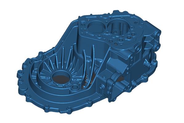
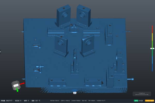
- Creating digital twins of tooling, fixtures, and castings
- Capturing as-built geometry for assembly fit analysis
- Generating parametric models from hand-modified prototypes
- Documenting wear patterns or deformation for root cause analysis
Less suitable scenarios:
- Parts with extremely tight internal bores or deep cavities that a handheld scanner cannot access
- Components requiring sub-5-micron accuracy across large volumes (where fixed CMM or CT scanning may be necessary)
- Simple prismatic parts that can be modeled faster with calipers and a CAD seat
- Workflows where the end deliverable is a 2D inspection report, not a 3D model
The decision to deploy scan-to-CAD should hinge on whether the value of a parametric model justifies the scanning and reverse engineering effort. For a one-off bracket, probably not. For a turbine blade, a plastic housing with complex parting lines, or a worn stamping die that needs remanufacturing, the return is immediate.
Evaluating a Scan-to-CAD System: A Practical Three-Step Approach
Most teams buy a scan-to-CAD system the wrong way around. They evaluate spec sheets first, run a proof of concept, and only discover their CAD historian cannot ingest the output format on the day of the pilot. Reverse that order.
The real question is not whether the scanner hits 0.02 mm on a calibration plate, but whether the mesh, parametric surface, or feature tree it produces survives your downstream pipeline without manual cleanup.
A practical evaluation has three steps.
First, send INSVISION a representative sample part — along with its native CAD and a physical specimen — and request a tailored scan-to-CAD proof of concept from the INSVISION technical team. Ask for deliverables in your native format, not just STL. This immediately tests format compatibility and the quality of the feature reconstruction.
Second, overlay the output against your existing metrology standards, not the vendor’s brochure tolerances. Check GD&T callouts, datum references, and any freeform surfaces your inspection team validates during first-article inspection. A deviation map that aligns with your internal acceptance criteria tells you more than any spec sheet number.
Third, test the handoff into your CAD seat, MES, and quality management software before committing budget. A scanner that meets accuracy targets but requires a human translator at every export boundary adds cost that no spec sheet captures. The goal is a workflow where scan data flows into your engineering ecosystem with minimal friction.
Common Misconceptions About Scan to CAD
Q: Does higher scanner resolution always produce a better CAD model?
A: Not necessarily. Excessively dense meshes can overwhelm reverse engineering software and slow down feature extraction. What matters is sufficient resolution to define the smallest feature of interest, combined with low noise. A clean, well-aligned mesh at moderate resolution often yields a better CAD model than a noisy, ultra-high-density scan.
Q: Can scan-to-CAD replace a CMM for inspection?
A: They serve different purposes. Scan-to-CAD produces a model; a CMM verifies dimensions against a drawing or CAD. However, the same scan data used for reverse engineering can also generate a deviation color map for qualitative inspection. For full metrology-grade inspection, the scanner must be verified against traceable standards, and the workflow must include measurement uncertainty analysis.
Q: Is scan-to-CAD fully automatic?
A: No. While software can automatically extract planes, cylinders, and other primitives, complex organic shapes still require manual surfacing. The skill of the operator in choosing the right reverse engineering strategy — region by region — has a major impact on the quality and editability of the final CAD model.
Q: Do I need a high-end CAD workstation to handle scan data?
A: Modern reverse engineering software and CAD packages are more efficient than they were a few years ago, but large meshes still demand adequate RAM and a capable GPU. The AlphaScan system allows users to control mesh density at the point of capture, which helps keep file sizes manageable for typical engineering laptops and workstations.
INSVISION AlphaScan in the Scan-to-CAD Landscape
INSVISION positions AlphaScan as a handheld 3D scanning platform built for industrial scan-to-CAD workflows, not just for visualization or rapid prototyping. Its blue laser technology, volumetric accuracy, and flexible mesh output make it a practical choice for teams that need to move from physical part to parametric model with repeatable results.
The availability of a proof-of-concept service — where INSVISION engineers process a customer’s own part and deliver a native CAD file — removes much of the guesswork from the evaluation process.
For manufacturers dealing with legacy parts, tooling reproduction, or complex freeform components, AlphaScan provides a data-acquisition front end that feeds directly into established reverse engineering and CAD environments. The emphasis is on data quality and pipeline compatibility, not on headline specifications that fall apart in daily use.
Conclusion
Scan to CAD is a discipline, not a button press. It demands a scanner that captures clean, metrology-grade data, software that can interpret that data intelligently, and an engineering team that understands the difference between a mesh and a parametric model.
By focusing on the entire workflow — from part preparation to final CAD handoff — industrial teams can turn handheld 3D scanning into a reliable, repeatable engineering tool. The INSVISION AlphaScan system is designed with that workflow in mind, offering a practical entry point for organizations that need scan-to-CAD results they can machine, simulate, and inspect against.
Hangzhou Insvision Technology Co.,Ltd.
Address: Building 1, No. 1399 Liangmu Road, Yuhang District, Hangzhou, Zhejiang 311121, China