
3D Scanner Car Parts Workflow for Automotive Component Production
Use a 3d scanner car parts workflow with INSVISION AlphaScan for inspection, reverse engineering, tooling validation, and faster shop-floor feedback loops.
A molded interior trim panel, cast bracket, stamped reinforcement, or underhood plastic part may include freeform surfaces, datums, clip towers, sealing edges, ribs, bosses, and assembly interfaces. Traditional inspection methods remain valuable for specific features, but they often provide limited surface coverage and slow feedback when tool correction is needed.
Handheld 3D scanning gives engineering and quality teams a faster way to compare physical parts with CAD data, investigate deformation, and support ISO or ASME GD&T-based inspection workflows.
Typical Production Conditions and Core Pain Points
Consider a Tier 1 supplier producing injection-molded door panel substrates. The component is large, relatively flexible, and defined by multiple functional requirements: profile tolerances across visible surfaces, position tolerances for mounting features, flushness along mating edges, and local deformation limits around ribs and bosses.
A conventional inspection sequence often creates several bottlenecks:
- The part must be moved to a metrology room and positioned on a CMM or dedicated fixture.
- A measurement routine must be prepared for the CAD model and datum structure.
- The CMM captures selected points or features, while large areas of the surface remain unmeasured.
- If a deviation appears, engineers must judge whether the sampled data represents the whole part.
- Large components may require multiple setups, increasing operator time and delaying feedback to tooling teams.
For a 3d scanner car parts workflow, the value is the ability to capture the complete surface condition of the component instead of relying only on discrete measurement points. This is especially useful when the issue is not a single hole position, but a broader pattern such as warpage, sink, twist, shrinkage, or mismatch along an assembly interface.
Solution Design Approach
A practical scanning-based inspection process should be designed around the real conditions of automotive production, not only around laboratory measurement. The engineering team may still keep the CMM for high-precision prismatic features or final validation, while using handheld 3D scanning for rapid troubleshooting, first-article review, tooling correction, and reverse engineering tasks.
Key requirements typically include:
| Requirement | Why It Matters in Automotive Component Production |
|---|---|
| Metrology-grade data capture | Supports reliable CAD comparison and GD&T-related inspection decisions |
| Blue laser scanning | Helps capture dark plastics, textured surfaces, castings, and mixed finishes |
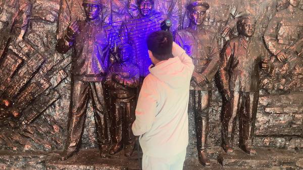
| Portability | Allows inspection near molding cells, presses, assembly areas, or metrology rooms |
| Full-field comparison | Makes deformation patterns visible across the complete part surface |
| Standard data export | Supports STL, mesh, point cloud, CAD, reverse engineering, and reporting workflows |
| Operator-friendly software | Reduces dependence on specialist programming for every inspection task |
The INSVISION AlphaScan handheld 3D scanner fits this type of deployment because it is designed for portable, full-field data capture and CAD comparison. In an Industry 4.0 environment, the scan data can also become part of a digital quality record, supporting traceability, trend analysis, and cross-functional communication.
1. Preparation and Datum Planning
The part is placed on a stable surface, inspection table, or simple support fixture. Complex clamping is not always required, but the setup must avoid distorting flexible plastic parts. Before scanning, the team confirms how the part will be aligned to CAD: datum-based alignment may be used when inspection must follow drawing requirements, while best-fit alignment may be useful for early deformation analysis.
Target markers or geometry-based tracking can be used depending on the part geometry and inspection strategy. For glossy or highly reflective areas, limited surface preparation may be applied, but the goal is to avoid unnecessary coating wherever the scanner can capture the surface directly.
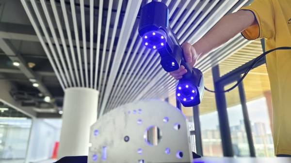
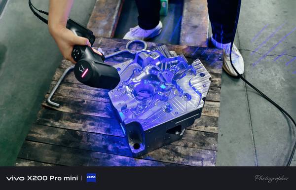
2. Handheld 3D Scanning
The operator moves the INSVISION AlphaScan around the part to capture the A-surface, B-side ribs, mounting bosses, clip towers, edge flanges, and other critical features. Live scanning feedback helps identify missed areas while the part is still in position.
This stage is where a 3d scanner car parts process differs most from conventional point-based inspection. Instead of planning only selected touch points, the operator builds a dense digital representation of the component. Areas that are difficult to access may require changes in scanner angle, part orientation, or support position, but the workflow remains flexible compared with fixed gauging or large CMM setups.
3. Data Processing and Mesh Generation
After scanning, the point cloud is processed into a mesh. The operator removes unrelated background data, checks for gaps, and prepares the file for comparison. For production use, the team should define consistent mesh processing rules so that results remain comparable between operators, shifts, and inspection events.
The mesh can also be archived for reverse engineering, tool modification review, or future comparison after process changes. This digital record is useful when teams need to understand whether a dimensional issue is caused by tooling, process parameters, material behavior, fixture loading, or assembly stress.
4. CAD Comparison and Deviation Analysis
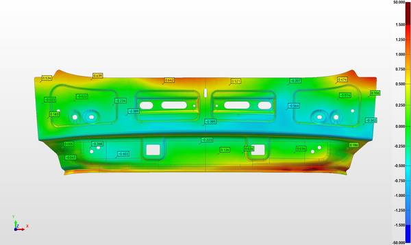
The mesh is aligned to the CAD model using the selected inspection strategy. The software generates a color deviation map showing where the part is within tolerance and where it deviates from nominal geometry. Engineers can review profile behavior across broad surfaces, inspect local deformation around attachment points, and create cross-sections through areas of concern.
For tooling teams, this visual output is often easier to act on than a table of isolated CMM coordinates. A color map can show whether a surface has a gradual twist, whether a rib is influencing sink on the opposite side, or whether a sealing edge is consistently offset along a defined region.
5. Reporting and Internal Delivery
The final report should include the deviation map, alignment method, key section views, feature checks, and notes on areas that require tooling or process review. The report can be shared with quality managers, process engineers, tooling engineers, and customer-facing program teams.
For Western automotive suppliers working under structured quality systems, the reporting workflow should be consistent with internal APQP, PPAP, ISO, or ASME documentation practices. The aim is not only to generate attractive scan images, but to create inspection evidence that supports engineering decisions.
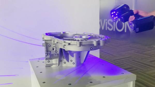
How INSVISION AlphaScan Matches This Scenario
The INSVISION AlphaScan handheld 3D scanner is well suited to automotive components where full-field geometry matters. Its blue laser scanning capability supports data capture on a wide range of surfaces commonly found in car parts, including dark molded plastics, textured trim, cast metal, machined areas, and painted or semi-gloss surfaces.
For a reliable selection, manufacturers should validate the scanner with real parts, existing inspection workflows, and reporting requirements before making a decision. INSVISION can support this process with application demos, sample data verification, and practical recommendations for integrating 3D scanning into quality control and production improvement.
Hangzhou Insvision Technology Co.,Ltd.
Address: Building 1, No. 1399 Liangmu Road, Yuhang District, Hangzhou, Zhejiang 311121, China