
Handheld 3D Scanning Technology for Industrial Metrology Applications
Explore handheld 3d scanning technology for inspection, reverse engineering, and shop-floor metrology with INSVISION AlphaScan workflows and validation.
Introduction: Industrial Measurement Under Shop-Floor Pressure
Manufacturers in automotive, aerospace, machinery, medical devices, energy, and contract manufacturing face a familiar metrology problem: parts are becoming more geometrically complex, while inspection windows are getting shorter.
Traditional contact measurement remains valuable for controlled feature checks, but it can become slow or incomplete when teams need to inspect freeform surfaces, welded assemblies, cast housings, composite parts, or additive manufacturing components.
Handheld 3D scanning technology gives engineering and quality teams a practical way to capture full-field geometry, compare as-built parts with CAD data, and create digital records that support lean manufacturing, Industry 4.0, and ISO/ASME-based quality workflows.
This article examines how INSVISION AlphaScan can be applied in realistic industrial measurement scenarios, from first-article inspection to reverse engineering and shop-floor quality checks.
Typical Work Conditions and Core Pain Points
In many Western manufacturing environments, dimensional inspection is no longer limited to a metrology room. Quality teams may need to measure a fabricated frame on the production line, verify a large casting before machining, or scan a legacy tool at a supplier site. These scenarios create practical constraints that influence the choice of measurement method.
| Work Condition | Limitation of Traditional Methods | Impact on Production or Engineering |
|---|---|---|
| Large or heavy parts | Moving parts to a CMM can require fixtures, lifting equipment, or schedule coordination | Inspection may be delayed or separated from the production process |
| Freeform surfaces | Contact probes collect discrete points and may miss localized deformation | Surface deviation, warp, and sink marks can remain under-characterized |
| Welded or assembled structures | Fixturing and datum setup can be difficult outside a controlled lab | Alignment and distortion checks may take longer than production teams can support |
| Legacy tooling without CAD | Manual measurement is slow and incomplete for complex shapes | Reverse engineering depends on partial data and engineering interpretation |
| Additive or organic geometries | Internal curves, thin edges, and irregular surfaces are difficult to probe | Go/no-go decisions may lack full geometric context |
For these conditions, 3D scanning technology is most valuable when it captures enough surface data to support decisions without forcing the part into a slow, lab-only process.
Solution Design for 3D Scanning Technology Deployment
A practical scanning solution should start with the measurement objective, not the equipment specification alone. Before deploying AlphaScan, teams should define the inspection requirement: whether the goal is CAD-to-part comparison, GD&T reporting, reverse engineering, fixture verification, supplier quality control, or maintenance documentation.
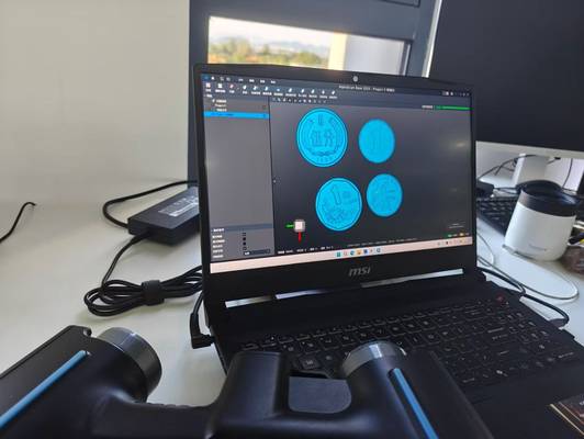
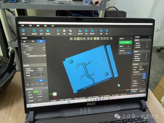
AlphaScan uses structured blue light to capture surface geometry. A calibrated light pattern is projected onto the part, while cameras record how that pattern changes across the surface. The software reconstructs the captured data into a dense point cloud and mesh, allowing technicians to see scan coverage as the model builds on screen.
This workflow helps operators identify missed regions during scanning rather than discovering gaps after the part has moved or left the work area.
For industrial buyers, the design question is whether the scanning workflow fits existing processes. A useful deployment plan should answer four points:
- What datum structure will be used for alignment?
- Which features require metrology reporting rather than visual comparison?
- Which file formats are needed for CAD, CAM, or metrology software?
- Who will operate the scanner during routine production or engineering tasks?
When these decisions are defined early, handheld 3D scanning technology becomes part of the inspection process rather than an isolated digital capture step.
1. Preparation
A successful scan begins with part selection and inspection planning. The engineering or quality team should choose representative components that reflect the real production challenge, such as a tight-tolerance machined feature, a warped molded surface, or a welded assembly that is difficult to move. Surface condition, part size, accessibility, and tolerance requirements should be reviewed before scanning.
For some surfaces, minimal preparation may be enough. Highly reflective, transparent, or very dark surfaces may still require additional handling depending on the inspection requirement. The goal is not to create an ideal demonstration condition, but to confirm how 3D scanning technology performs under the same constraints technicians face during routine work.
2. Scanning
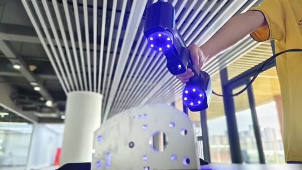
During scanning, the operator moves AlphaScan around the part to capture geometry from multiple angles. Real-time feedback helps confirm coverage and reduces the risk of missing hidden edges, pockets, or underside features.
For large parts or assemblies, the scan can often be performed near the production line, at a workstation, or at a supplier facility, reducing the need to move heavy components to a dedicated measurement room.
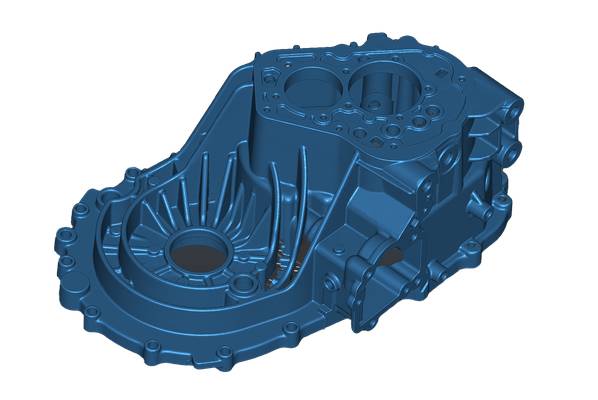
This step is especially useful for parts where a CMM program would require extensive fixturing or multiple setups. Instead of collecting only selected probe points, AlphaScan generates a full-field data set that can reveal local distortion, surface waviness, and unexpected deformation.
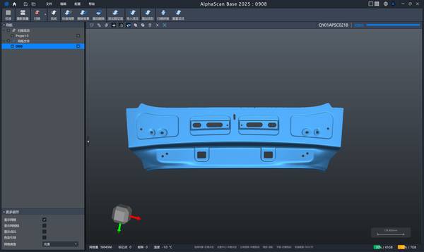
3. Data Processing
After capture, the scan data is processed into a mesh that can be used for CAD comparison, dimensional inspection, or reverse engineering. Alignment should follow the same inspection logic used in the existing quality process, such as datum-based alignment, feature-based alignment, or best-fit alignment depending on the inspection plan and tolerance requirements. This ensures that scan results can be compared consistently with CAD models, historical batches and customer quality documents.
Hangzhou Insvision Technology Co.,Ltd.
Address: Building 1, No. 1399 Liangmu Road, Yuhang District, Hangzhou, Zhejiang 311121, China