
Closing the Dimensional Gap on the Production Floor with Handheld 3D Scanning Tools
Discover how handheld 3D scanning tools like INSVISION AlphaScan and AlphaVista streamline aerospace and automotive inspection workflows on the production floor.
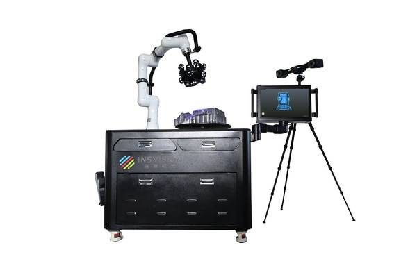
Handheld 3D scanning tools have moved from prototyping curiosity to primary inspection asset in these environments. Not because they replace every legacy gauge, but because they close the data gap on freeform surfaces, welded assemblies, and large workpieces—delivering dense point clouds and actionable deviation maps within production cycle windows.
This article walks through two real-world scenarios where INSVISION scanning systems changed how quality teams approach dimensional verification, and what that means for engineers evaluating similar deployments.
Aerospace Component Repair: Rebuilding Without Original CAD
A turbine blade repair facility receives worn airfoils with eroded leading edges and distorted profiles. The original design data is often unavailable—the blades may be legacy parts, or the OEM never released the nominal geometry. The repair process requires restoring the airfoil to print, which means first understanding exactly where material is missing and where it remains within tolerance.
Capability and Deployment Mapping
| Focus Area | Decision Point | Deployment Note |
|---|---|---|
| Aerospace Component Repair: Rebuilding Without Original… | A turbine blade repair facility receives worn airfoils with eroded leading edges and distorted profiles. | The original design data is often unavailable—the blades may be legacy parts, or the OEM never released the nominal geometry. |
| Automotive First-Article Inspection: The CMM Bottleneck | At a Tier-1 stamping supplier, first-article approval runs follow a familiar rhythm. | The die set produces a handful of parts, and the quality team rushes them to the CMM lab. |
| A Different Approach: Integrated 3D Scanning Workflows | The shift in both scenarios is from sparse point measurement to full-field surface capture using 3D scanning tools. | These handheld devices project structured light or laser patterns onto the part, record millions of points in seconds, and build a dense mesh th… |
The traditional approach relies on manual templating and sectional gauges. A technician places the blade against a series of physical templates, checks gaps with feeler gauges, and marks high spots for grinding. This method is slow, operator-dependent, and generates no digital record of the as-received condition.
It also cannot produce a full-field deviation map that shows how the entire surface relates to a reference geometry. Without that map, the repair shop cannot optimize material deposition or machining paths, and quality documentation remains a paper trail of pass/fail checks rather than a traceable dimensional report.
Automotive First-Article Inspection: The CMM Bottleneck
At a Tier-1 stamping supplier, first-article approval runs follow a familiar rhythm. The die set produces a handful of parts, and the quality team rushes them to the CMM lab. Programming the CMM for a new part with multiple contoured surfaces takes hours. The probe touches a few dozen points per feature, leaving the areas between points uninspected.
If the CMM report flags a dimension out of tolerance, the team must decide whether the part is truly nonconforming or whether the sparse sampling missed the true surface profile. Meanwhile, the stamping line sits idle, waiting for approval to begin the full batch.
The core pain point is not accuracy—CMMs are highly accurate. It is throughput and coverage. A first-article inspection that takes four hours on a CMM might need to happen in 30 minutes to keep production flowing. The quality manager needs confidence that the entire surface, not just a few sampled points, conforms to the CAD model.
Sparse probing on a contoured bracket can miss springback deviations that later cause assembly fit issues downstream.
A Different Approach: Integrated 3D Scanning Workflows
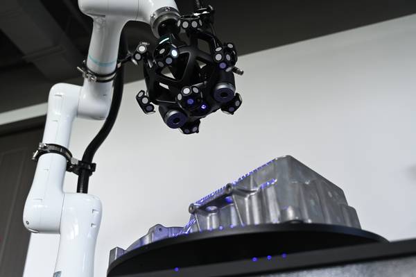
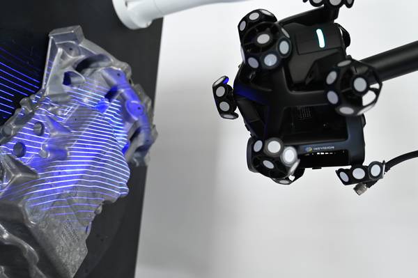
The shift in both scenarios is from sparse point measurement to full-field surface capture using 3D scanning tools. These handheld devices project structured light or laser patterns onto the part, record millions of points in seconds, and build a dense mesh that represents the actual geometry. This mesh is then aligned to a CAD reference—or, in the case of reverse engineering, used to reconstruct a CAD model from scratch.
For the turbine blade repair cell, the workflow starts with scanning the damaged blade. The resulting point cloud is compared against a reference geometry, which could be a scan of a known-good blade or a nominal model generated from
Hangzhou Insvision Technology Co.,Ltd.
Address: Building 1, No. 1399 Liangmu Road, Yuhang District, Hangzhou, Zhejiang 311121, China