
Large Part 3D Scanning
Large part 3D scanning focuses on capturing surface geometry for components or assemblies that exceed the field of view or workspace of conventional.
Definition
Large part 3D scanning is a specialized category of industrial 3D digitization technology focused on capturing measurement-quality three-dimensional geometric data of large-scale industrial components, assemblies, and assets. It is designed to address the unique challenges of scanning objects that exceed the field of view of standard 3D scanning systems, including controlling accumulated error across large measurement volumes, operating in varied industrial environments, and capturing both full-scale geometry and relevant fine features. Common downstream applications include dimensional quality inspection, reverse engineering of legacy components, uneven wear assessment, and digital twin creation for industrial assets.
How It Works
Large part 3D scanning relies on a unified global coordinate framework to reduce cumulative alignment error across multiple scan segments, as no single scan can capture the full geometry of a large workpiece. The general workflow follows three core stages:
- Global Reference Setup: Calibrated reference markers, scales, or optical tracking targets are positioned on or around the workpiece to establish a fixed, unified coordinate system that spans the full measurement volume. This reference frame eliminates drift that occurs when stitching individual scans without a common reference.
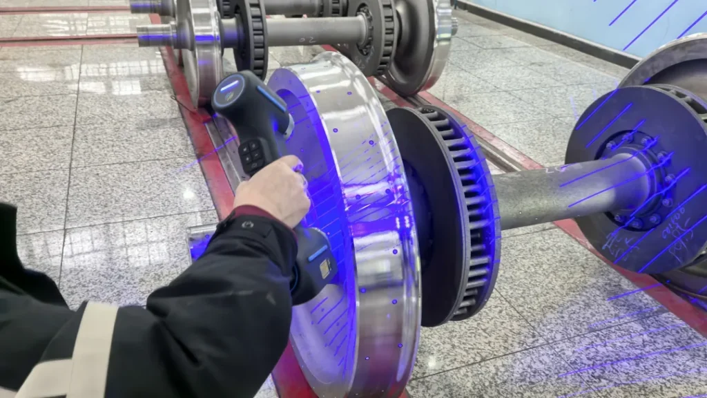
- Sequential Data Capture: A 3D scanning device (available in handheld, stationary structured light, optically tracked, or automated configurations) captures overlapping sections of the workpiece surface. The device continuously aligns each scan segment to the global coordinate system in real time, removing the need for manual post-processing alignment. Modern systems often integrate software algorithms to automate feature detection, noise reduction, and alignment optimization.
- Data Reconstruction and Processing: Raw point cloud or mesh data is processed to remove environmental noise, fill minor surface gaps, and merge all scan segments into a single, complete 3D representation of the workpiece. The resulting digital model can then be exported for downstream industrial applications.
Key Parameters and Criteria
The performance of large part 3D scanning systems is evaluated using standardized, measurable parameters tailored to the unique requirements of scanning across large volumes. Key parameters and their evaluation methods are outlined below:
| Parameter | Meaning | Judgment Method |
|---|---|---|
| Volume Accuracy | The maximum allowable deviation between scanned measurements and calibrated reference values across the full scanned volume, accounting for cumulative alignment error across multiple scan segments. | Verified by measuring calibrated reference artifacts of dimensions matching the target scan volume, with results reported as a fixed base deviation plus a per-meter scaling factor (e.g., 0.1 mm ± 0.015 mm/m) per standardized industrial calibration procedures. |
| Maximum Scan Field of View | The maximum surface area that can be captured in a single scan pass, directly impacting the total number of scans required to cover a large workpiece. | Measured as the horizontal and vertical dimensions of the capture area at the device’s optimal working distance, reported in square millimeters. |
| Scan Rate | The number of 3D measurement points captured per second, directly impacting the total time required to complete a full scan of a large workpiece. | Measured under controlled standard test conditions, reported as measurements per second. |
| Global Coordinate Stability | The ability of the system to maintain consistent alignment of all scan segments to the unified global coordinate frame across the full scanning workflow, preventing position drift over large volumes. | Verified by measuring the position of fixed reference markers at multiple points across the scan volume before and after a complete scanning workflow, then calculating the maximum deviation in marker position measurements. |
| Point Density Uniformity | The consistency of 3D point distribution across the entire surface of the workpiece, including curved surfaces, edges, and hard-to-reach areas. | Calculated by comparing the number of points per square millimeter across multiple randomly selected regions of the reconstructed 3D model, with deviations reported as a percentage of the target point density. |
Suitable and Unsuitable Scenarios
Suitable Scenarios
- Dimensional quality inspection of large industrial assemblies, including aerospace structural components, automotive body panels, heavy machinery castings, and energy equipment parts
- Reverse engineering of large legacy industrial components without existing CAD models
- Uneven wear assessment of large operational assets, such as wind turbine blades, mining equipment, and heavy machinery components
- In-situ scanning of large equipment in harsh industrial environments where fixed coordinate measuring machines cannot be deployed, including environments with high temperatures, dust, or explosive atmospheres
- Digital twin creation for large industrial assets for predictive maintenance and process optimization
Unsuitable Scenarios
- Scanning of small industrial components with maximum dimensions less than 10 cm
- Non-industrial applications including human body or facial scanning
- Medical imaging diagnostic applications
- Inspection of tiny holes with diameters less than 5 mm
Common Misconceptions
- Misconception: Large part 3D scanning is inherently less accurate than small-part 3D scanning.
Correction: Modern large part 3D scanning systems are calibrated to maintain high precision across large volumes using global coordinate frameworks, with volume accuracy specifications that scale with measurement size. When configured appropriately for the use case, large part scanning can deliver precision comparable to small-part scanning for industrial applications.
- Misconception: Large part 3D scanning requires fixed, stationary scanning equipment installations.
Correction: Multiple system configurations are available to suit varied use cases, including portable handheld scanners, optically tracked mobile systems, and fixed automated systems. Portable configurations allow for on-site, in-situ scanning of large assets that cannot be moved to a dedicated inspection area.
- Misconception: Large part 3D scanning only captures coarse overall geometry, not fine surface or geometric features.
Correction: High-performance large part scanning systems support adjustable scan resolution and point density, allowing users to capture both the full-scale geometry of large workpieces and fine surface features as required for specific inspection or reverse engineering applications.
Related Concepts
- Industrial 3D Digitization: The broader process of converting physical industrial objects into digital 3D representations, of which large part 3D scanning is a specialized subset.
- Optical Tracking Systems: Systems that use calibrated cameras and reference markers to track the position of scanning devices in 3D space, used to establish global coordinate frames for large volume scanning.
- Structured Light 3D Scanning: A scanning technology that projects patterned light onto objects and captures pattern deformations to calculate 3D geometry, often used for high-precision large part scanning applications.
- Reverse Engineering: The process of generating a CAD model from a scanned 3D representation of a physical object, a common downstream application of large part 3D scanning.
- Dimensional Quality Inspection: The process of comparing a scanned 3D model to a reference CAD model to verify compliance with design tolerances, a core use case for large part 3D scanning.
- Digital Twin: A virtual replica of a physical industrial asset, often created using data from large part 3D scanning, used for monitoring, predictive maintenance, and process optimization.
FAQ
What is the maximum size of workpiece that can be scanned with large part 3D scanning?
There is no universal fixed maximum workpiece size, as the measurement volume can be extended by adding additional reference markers or expanding the range of optical tracking systems. The maximum practical scan size depends on the system configuration, reference setup, and required accuracy for the specific application.
Can large part 3D scanning be performed on-site in harsh industrial environments?
Yes, many large part 3D scanning systems are designed for portable, in-situ use across a range of industrial environments. Suitability for specific harsh conditions (such as high temperatures, dust, or explosive atmospheres) depends on the system’s environmental ratings and certifications.
How does large part 3D scanning avoid cumulative alignment error across multiple scans?
Large part 3D scanning systems use a unified global coordinate frame established via reference markers, calibrated scales, or optical tracking systems to align each scan segment in real time. This eliminates the cumulative drift that would occur from stitching individual scans without a common global reference.
Can large part 3D scanning capture both full-scale geometry and fine surface details?
Yes, modern large part 3D scanning systems support adjustable scan resolution and point density, allowing users to capture both the overall geometry of large workpieces and fine surface or geometric features as required for specific applications.
Summary
Large part 3D scanning is a specialized industrial 3D digitization technology designed to capture high-precision geometric data of large-scale industrial components, assemblies, and assets. It addresses the unique challenges of controlling accumulated error across large measurement volumes and operating in varied industrial environments, supporting core applications including dimensional quality inspection, reverse engineering, wear assessment, and digital twin creation. System performance is evaluated via standardized parameters including volume accuracy, scan field of view, and global coordinate stability, with multiple configurations available to suit different use cases, from portable handheld systems for on-site scanning to automated systems for repeated factory-floor inspection.
- What Is 3D Scanning? Principles, Workflow, and Industrial Applications 3D scanning is a digital measurement technology that converts the surface geometry of physical objects into 3D data. This entry covers its working principles, core parameters, industrial use cases, common misconceptions, and related technical…
- What Is a 3D Scanner? Types, Parameters, and Selection Criteria A 3D scanner captures three-dimensional surface data from physical objects and converts geometry, dimensions, and features into digital data for inspection, reverse engineering, and modeling.
- What Is 3D Scanning Accuracy? Accuracy, Repeatability, and Resolution Explained 3D scanning accuracy describes how closely scan data matches an object's actual geometry and dimensions. It is assessed through local accuracy, volumetric accuracy, stitching accuracy, repeatability, and resolution.
- What Is Point Cloud Data? Point Clouds, Meshes, and CAD Models in 3D Scanning Point cloud data is an important raw data format in 3D scanning. It consists of discrete 3D coordinate points that describe object surface geometry and support inspection, reverse engineering, modeling, and archiving.
Hangzhou Insvision Technology Co.,Ltd.
Address: Building 1, No. 1399 Liangmu Road, Yuhang District, Hangzhou, Zhejiang 311121, China