
Structured Light 3D Scanning
Structured light 3D scanning uses projected patterns and cameras to reconstruct object geometry for inspection and reverse engineering.
Definition
Structured light 3D scanning is a non-contact optical 3D digitization technique that reconstructs the three-dimensional geometry of physical objects by analyzing distortions in projected light patterns. In industrial use, it is commonly selected when dense surface data, repeatable measurement, and efficient capture are needed across suitable component sizes and application workflows.
How It Works
Structured light 3D scanning systems typically combine one or more calibrated optical projectors, one or more cameras, and dedicated processing software. Configurations may use single-camera or multi-camera layouts depending on field of view, accuracy requirements, and system design. The standard workflow proceeds as follows:
- System Calibration: Prior to scanning, the system is calibrated to establish the spatial relationship between the projector(s) and cameras, and to define reference coordinates for measurement. Calibration is typically performed using certified reference artifacts, and may be automated on modern industrial systems.
- Pattern Projection: The projector casts a sequence of predefined structured light patterns, such as sinusoidal fringe patterns or binary grid patterns, onto the surface of the target object. Many industrial systems use narrowband blue light because it can reduce sensitivity to some ambient light interference compared with broadband white light.
- Distortion Capture: The synchronized cameras record the light patterns as they appear on the object’s surface, where the object’s topography distorts the shape of the projected patterns.
- 3D Reconstruction: Processing software uses triangulation, phase analysis, filtering, and calibration data to calculate 3D coordinates on the object's surface from the observed pattern distortions.
- Data Output: The system outputs a dense point cloud, which may be further processed into a polygon mesh or surfaced 3D model for downstream applications.
Key Parameters and Criteria
The performance of structured light 3D scanners is evaluated against standardized, measurable parameters, all of which may vary based on object material, surface finish, ambient environment, working distance, and system configuration. Core parameters are defined below:
| Parameter | Meaning | Judgment Method |
|---|---|---|
| Measurement Accuracy | The maximum permissible deviation between a scanned 3D measurement and the certified nominal value of a reference artifact | Verified with calibrated reference artifacts and applicable optical metrology test methods under controlled test conditions |
| Scanning Field of View (FoV) | The maximum surface area of an object that can be captured in a single scan pass | Defined via system calibration, with values adjusted by lens configuration and working distance for a given use case |
| Scan Rate | The number of valid 3D coordinate points captured per second by the system | Measured under specified test conditions using a reference object or representative workpiece, reported for the relevant scan mode |
| Point Cloud Density | The number of discrete 3D points per unit area of the scanned object’s surface | Calculated from raw scan output, adjustable via software settings to prioritize high detail for fine features or faster processing for large components |
| Volume Accuracy | The cumulative measurement deviation across the full working volume of the scanner, relevant for large object scanning | Tested using calibrated length artifacts or reference targets placed at multiple positions and orientations within the system's specified working volume |
Suitable and Unsuitable Scenarios
Structured light 3D scanning has defined use case boundaries based on object geometry, size, and application requirements.
Suitable Scenarios
- Industrial reverse engineering for components whose size, surface condition, and required tolerance match the scanner field of view and resolution
- Dimensional quality inspection for automotive, aerospace, energy, and advanced manufacturing parts
- Batch 3D digitization and validation for 3D printed components
- Uneven wear, corrosion, and damage assessment for industrial tooling and field assets
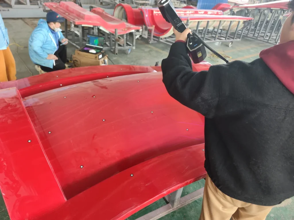
- Large structural component inspection, including aircraft fuselage sections and automotive body panels
- On-site inspection in controlled or harsh industrial environments, when using ruggedized system configurations
Unsuitable Scenarios
- Objects or features smaller than the scanner's resolvable limit for the selected field of view and working distance
- Internal features, deep holes, and occluded geometry that cannot be directly observed by the cameras from available scan angles
- Non-industrial human body or facial scanning use cases
- Medical imaging diagnostic applications
- Highly specular reflective or fully transparent surfaces, unless a temporary matte coating is applied to the object prior to scanning
Common Misconceptions
- Misconception: All structured light 3D scanners deliver equivalent performance across all use cases.
Correction: Scanning systems are tuned for specific applications; hardware optimized for large-volume scanning will not deliver the same fine-feature resolution as a system designed for small component inspection, and vice versa.
- Misconception: Structured light scanning can only be used in dark, controlled lab environments.
Correction: Many industrial structured light systems use controlled projection, filtering, and exposure settings to work in typical factory floor lighting, though direct sunlight or high-intensity ambient light may still impact measurement accuracy.
- Misconception: Structured light scanning can capture all surface geometry without occlusion issues.
Correction: Undercuts, deep crevices, and surfaces blocked by other features will not be captured in a single scan pass, requiring repositioning of the scanner or target object to capture occluded areas.
- Misconception: Higher scan rates always result in better workflow efficiency.
Correction: Scan rate is often balanced with point density and accuracy; maximum scan rate settings may reduce the resolution of captured data, so optimal settings depend on the specific requirements of the use case.
Related Concepts
- Laser 3D Scanning: A complementary non-contact 3D digitization technique that uses projected laser points or lines instead of structured light patterns. It may be preferred for certain long-range, outdoor, moving-object, or difficult-surface scenarios, depending on the system design and application requirement.
- Photogrammetry: A 3D reconstruction method that uses overlapping 2D photographs of an object captured from multiple angles, rather than projected light, most commonly used for mapping very large outdoor structures such as buildings or infrastructure.
- Point Cloud: The raw output of most 3D scanning processes, consisting of a set of georeferenced 3D coordinate points that represent the surface geometry of the scanned object, used as the basis for further processing into meshes or surfaced models.
- GD&T (Geometric Dimensioning and Tolerancing): A standardized system for defining and communicating engineering design tolerances, commonly applied to 3D scan data to perform pass/fail quality inspection for manufactured components.
- Optical Tracking: A technology that uses fixed cameras and reference markers to track the position of a mobile 3D scanner in 3D space, helping reduce manual alignment work across multiple scan passes when scanning large objects.
FAQ
What is the difference between blue light and white light structured light scanning?
Blue light structured light systems use narrowband blue wavelength projection, which can be less susceptible to some ambient lighting interference than broadband white light sources. White light systems may still be suitable in controlled environments, while the best choice depends on the scanner design, surface material, lighting conditions, and accuracy requirement.
Can structured light 3D scanning be used for reflective or transparent objects?
Standard industrial structured light systems typically produce incomplete or noisy scan data for highly specular reflective or fully transparent surfaces, as projected light patterns are either reflected away from the system’s cameras or pass through the object. These surfaces can usually be scanned after application of a temporary thin matte coating, though this step adds additional preparation time to the workflow.
How does structured light 3D scanning compare to laser 3D scanning for industrial inspection?
Structured light scanning can capture dense point clouds efficiently for stationary components when the field of view and surface conditions are suitable. Laser scanning may be preferred for some long-range, outdoor, moving-object, or difficult-surface scenarios. The better method depends on working distance, accuracy target, surface finish, scan speed, and workflow constraints.
Does structured light 3D scanning require physical contact with the target object?
No, structured light 3D scanning is a fully non-contact technology, making it suitable for scanning fragile, soft, or high-value components that cannot be touched or repositioned without risk of damage or deformation.
Summary
Structured light 3D scanning is a non-contact optical 3D digitization technology used for industrial reverse engineering, quality inspection, and asset assessment. Its performance depends on measurable parameters such as accuracy, field of view, scan rate, point density, working distance, surface condition, and calibration quality. Suitable hardware configurations may include handheld, automated, and large-volume tracking-enabled systems tailored to specific workflow requirements.
- What Is 3D Scanning? Principles, Workflow, and Industrial Applications 3D scanning is a digital measurement technology that converts the surface geometry of physical objects into 3D data. This entry covers its working principles, core parameters, industrial use cases, common misconceptions, and related technical…
- What Is a 3D Scanner? Types, Parameters, and Selection Criteria A 3D scanner captures three-dimensional surface data from physical objects and converts geometry, dimensions, and features into digital data for inspection, reverse engineering, and modeling.
- What Is 3D Scanning Accuracy? Accuracy, Repeatability, and Resolution Explained 3D scanning accuracy describes how closely scan data matches an object's actual geometry and dimensions. It is assessed through local accuracy, volumetric accuracy, stitching accuracy, repeatability, and resolution.
- What Is Point Cloud Data? Point Clouds, Meshes, and CAD Models in 3D Scanning Point cloud data is an important raw data format in 3D scanning. It consists of discrete 3D coordinate points that describe object surface geometry and support inspection, reverse engineering, modeling, and archiving.
Hangzhou Insvision Technology Co.,Ltd.
Address: Building 1, No. 1399 Liangmu Road, Yuhang District, Hangzhou, Zhejiang 311121, China