
Industrial Standards for Using a 3D Scanner to Make STL Files in 2026
Discover 2026 industrial standards for using a 3D scanner to make STL files. Learn how to bridge raw scan data to validated, watertight meshes for manufacturing.
Core Concepts and Workflow of a 3D Scanner to Make STL Files
The process of creating an STL file from a 3D scanner is a multi-stage digital reconstruction pipeline, not a single export function. It transforms a physical object’s geometry into a watertight, faceted mesh model suitable for downstream engineering software.
The core workflow involves four sequential stages:
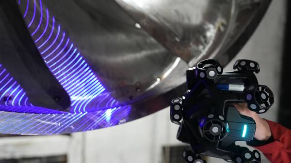
- Data Acquisition: A scanner using structured light or laser triangulation captures millions of coordinate points from the object’s surface, generating a raw point cloud.
- Data Processing and Cleaning: Specialized software filters this cloud to remove optical noise, outliers, and artifacts caused by reflections or shadows, while filling minor data gaps.
- Mesh Generation and Optimization: The clean point cloud is triangulated into a polygon mesh. This mesh undergoes decimation (reducing polygon count while preserving critical features) and smoothing to achieve an optimal balance between file size and geometric fidelity.
- Sealing and Validation: The final step is watertight sealing—ensuring the mesh is a complete, boundary-representation solid with no holes or non-manifold edges. An unsealed mesh will fail in slicers, CAM software, or metrology platforms.
Critical Technical Elements for Industrial-Grade STL Files
Not all outputs from a 3d scanner to make stl files are equal. Industrial acceptance depends on several quantifiable and qualifiable elements:
| Element | Industrial Requirement | Impact |
|---|---|---|
| Accuracy and Resolution | Mesh resolution must match application tolerance. For critical AM features, facet deviation often needs to be within 0.025–0.050mm. | Defines the dimensional accuracy of the final printed or machined part. |
| Mesh Integrity | A fully watertight, manifold mesh is non-negotiable. | Ensures compatibility with all downstream software for manufacturing and analysis. |
| Data Traceability | The entire scan-to-mesh process must align with metrology standards (e.g., ISO 10360 for equipment verification). | Provides documented confidence for quality-critical sectors like aerospace and automotive. |
| Workflow Efficiency | Minimized manual intervention between scan and final STL export. | Reduces engineering time and accelerates time-to-decision or time-to-production. |
Differences Between Scan-to-STL and CAD-to-STL
The key distinction lies between 3D scanning for STL generation and traditional CAD-based STL creation. A 3d scanner to make stl files captures as-built or as-designed physical geometry, including complex organic forms, wear patterns, and subtle deformations. It is essential for reverse engineering, first-article inspection, and digitizing legacy parts.
CAD-to-STL exports a theoretical, nominal model from original design software, representing ideal geometry without real-world deviations.
Appropriate and Inappropriate Applications
Appropriate Applications:
- Reverse Engineering and Digital Archiving: Creating CAD models from physical prototypes or legacy parts with no existing drawings.
- First-Article Inspection and Deviation Analysis: Generating a reference mesh from a master part to compare against production runs.
- Custom Tooling and Fixturing: Scanning interfaces to design perfectly fitting jigs, fixtures, or custom tooling.
- Additive Manufacturing Repair and Modification: Digitizing a worn part for repair or modification before printing a replacement.
Inappropriate Applications:
- Creating parts with entirely new, parametric geometries from scratch (use CAD).
- Applications requiring perfect geometric primitives (e.g., ideal planes, cylinders) without any surface noise.
- When the required final deliverable is a parametric, feature-based CAD model rather than a mesh (scan data requires conversion).
Selection Criteria for Industrial Buyers
When evaluating a 3d scanner to make stl files, selection should be driven by workflow integration and compliance needs rather than headline resolution specifications.
- Certifications and Standards: Verify hardware carries necessary safety (e.g., Class I/II Laser, CE, FCC) and software carries metrological traceability certifications (e.g., PTB) relevant to your industry and region.
- Software Ecosystem: The scanner’s native software should automate the cleaning, sealing, and optimization pipeline. Needing multiple third-party applications to achieve a watertight STL introduces error risk and inefficiency.
- Output Matching: Ensure the system can generate STLs tailored to your specific need—whether it is a lightweight mesh for visualization, a high-resolution mesh for inspection, or an optimized mesh for CAD conversion.
INSVISION Capabilities and Technology Approach
INSVISION systems are engineered to address this integrated scan-to-STL challenge. The technology integrates high-fidelity data acquisition with an automated software pipeline designed to minimize manual post-processing. The focus is on embedding compliance checkpoints within the workflow, aligning data processing with standards like ISO 10360 for measurement integrity and ASME Y14.5 for GD&T intent preservation.
This approach reduces cycle time in first-article inspection and streamlines approval processes within regulated supply chains by delivering documented, traceable STL outputs.
Common Misconceptions and Technical FAQ
Q: If my scanner has high accuracy, does that guarantee a good STL file?
A: No. Scanner accuracy refers to the fidelity of the raw point cloud. A high-accuracy scan can still produce a non-watertight or poorly optimized mesh if the post-processing software is inadequate. The entire workflow determines the final STL quality.
Q: Can I use a scanned STL file directly for CNC machining?
A: Typically, no. Most CAM systems require watertight, error-free meshes. Using a 3d scanner to make stl files for CNC machining requires meticulous cleaning and sealing first. Furthermore, for precision machining, the STL often serves as a reference for creating toolpaths in dedicated CAM software, rather than being used directly.
Q: What is the biggest bottleneck in creating production-ready STL files from scans?
A: The manual labor of data cleaning and mesh repair. Operating a 3d scanner to make stl files efficiently requires systems that offer automated noise filtering, outlier removal, and one-click watertight sealing to accelerate the process and reduce the risk of human error.
Conclusion
Generating industrial-grade STL files from a 3D scanner is a disciplined engineering process, not a simple button press. Success depends on understanding the technical pipeline from point cloud to sealed mesh, adhering to relevant metrology and safety standards, and selecting a system whose software automates the transition from raw data to validated output.
For engineers in quality-critical industries, the value lies not just in capturing geometry, but in efficiently producing a reliable, traceable digital asset that integrates seamlessly into stringent manufacturing and inspection workflows when using a 3d scanner to make stl files.
Hangzhou Insvision Technology Co.,Ltd.
Address: Building 1, No. 1399 Liangmu Road, Yuhang District, Hangzhou, Zhejiang 311121, China